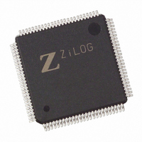
Z8018216ASC Zilog, Z8018216ASC Datasheet - Page 73

Z8018216ASC
Manufacturer Part Number
Z8018216ASC
Description
IC 16MHZ STATIC MIMIC 100-LQFP
Manufacturer
Zilog
Datasheet
1.Z8018233FSG.pdf
(109 pages)
Specifications of Z8018216ASC
Processor Type
Z180
Features
Smart Peripheral Controller
Speed
16MHz
Voltage
5V
Mounting Type
Surface Mount
Package / Case
100-LQFP
Lead Free Status / RoHS Status
Contains lead / RoHS non-compliant
Available stocks
Company
Part Number
Manufacturer
Quantity
Price
Line Control Register
Bit 7 Divisor Latch Access Bit (DALB)
This bit allow access to the divisor latch by the PC/XT/AT.
If this bit is set to 1, access to the Transmitter, Receiver and
Interrupt Enable Registers is disabled. When an access is
made to address 0 the Divisor Latch Least Significant byte
is accessed. If an access is made to address 1, the Divisor
Latch Most Significant byte is accessed.
Bit 6 - Bit 0
These bits do not affect the Z80182/Z8L182 directly,
however they can be read by the Z180 MPU and the 16550
MIMIC modes can be emulated by the Z180 MPU.
DS971820600
Zilog
D7 D6 D5 D4 D3 D2 D1 D0
(Z180 MPU Read Only, Address xxF3H)
(Z180 MPU Read Only, Address xxF4H)
0
Figure 77. Modem Control Register
D7 D6 D5 D4 D3 D2 D1 D0
0
Figure 76. Line Control Register
0
(PC Read/Write, Address 03H)
(PC Read/Write, Address 04H)
0
0
0
0
0
0
0
0
0
0
0
0
0
Word Length Sel.
# of Stop Bits
Even Parity Sel.
Stick Parity
Set Break
Parity Enable
DALB
DTR
RTS
Out 1
Out 2
Loop
Reserved
P R E L I M I N A R Y
PS009801-0301
Modem Control Register
Bit 7-5 Reserved
Reserved for future use, always 0.
Bit 4 Loop
When this bit is set to 1, D3-D0 field reflects the status of
Modem Status Register, as follows:
Emulation of the 16550 UART loop back feature must be
done by the Z180 MPU, except in the above conditions.
Bit 3 Out 2
This bit controls the tri-state on the HINTR pin if bits 2 and
1 are 10. Otherwise it can be read by the Z180 MPU.
Bits 2, 1, 0
These bits have no direct control of the 16550 MIMIC
interface and the Z180 MPU must emulate the function if
it is to be implemented.
(Z180 MPU Read/Write bits 7-4, Address xxF6H)
Figure 78. Modem Status Register
D7 D6 D5 D4 D3 D2 D1 D0
0
(PC Read Only, Address 06H)
0
DCD = Out 2
DSR = DTR
CTS = RTS
0
RI = Out 1
0
0
0
0
Z
ILOG
0
I
NTELLIGENT
DCTS
DDSR
TERI
DDCD
CTS
DSR
DCD
RI
Z80182/Z8L182
P
ERIPHERAL
3-73


