FDC37C665GT-MS SMSC, FDC37C665GT-MS Datasheet - Page 44
FDC37C665GT-MS
Manufacturer Part Number
FDC37C665GT-MS
Description
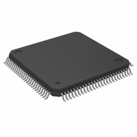
IC CTRLR SUPER I/O MULTI 100-QFP
Manufacturer
SMSC
Datasheet
1.FDC37C665GT-MS.pdf
(152 pages)
Specifications of FDC37C665GT-MS
Controller Type
I/O Controller
Interface
ISA Host
Voltage - Supply
4.5 V ~ 5.5 V
Current - Supply
35mA
Operating Temperature
0°C ~ 70°C
Mounting Type
Surface Mount
Package / Case
100-QFP
Lead Free Status / RoHS Status
Lead free / RoHS Compliant
Other names
638-1007
Available stocks
Company
Part Number
Manufacturer
Quantity
Price
Company:

Part Number:
FDC37C665GT-MS
Manufacturer:
Microchip Technology
Quantity:
10 000


A low threshold value (i.e. 2) results in longer
periods of time between service requests, but
requires faster servicing of the request for both
read and write cases. The host reads (writes)
from (to) the FIFO until empty (full), then the
transfer request goes inactive. The host must
be very responsive to the service request. This
is the desired case for use with a "fast" system.
A high value of threshold (i.e. 12) is used with a
"sluggish" system by affording a long latency
period after a service request, but results in
more frequent service requests.
Non-DMA Mode - Transfers from the FIFO to
the Host
The FINT pin and RQM bits in the Main Status
Register are activated when the FIFO contains
(16-<threshold>) bytes or the last bytes of a full
sector have been placed in the FIFO. The FINT
pin can be used for interrupt-driven systems,
and RQM can be used for polled systems. The
host must respond to the request by reading
data from the FIFO. This process is repeated
until the last byte is transferred out of the FIFO.
bit when the FIFO becomes empty.
Non-DMA Mode - Transfers from the Host to the
FIFO
The FINT pin and RQM bit in the Main Status
Register are activated upon entering the
execution phase of data transfer commands.
The host must respond to the request by writing
data into the FIFO. The FINT pin and RQM bit
remain true until the FIFO becomes full. They
are set true again when the FIFO has
<threshold> bytes remaining in the FIFO. The
FINT pin will also be deactivated if TC and
nDACK both go inactive. The FDC enters the
result phase after the last byte is taken by the
FDC from the FIFO (i.e. FIFO empty condition).
The FDC will deactivate the FINT pin and RQM
44
DMA Mode - Transfers from the FIFO to the
Host
The FDC activates the FDRQ pin when the FIFO
contains (16 - <threshold>) bytes, or the last
byte of a full sector transfer has been placed in
the FIFO. The DMA controller must respond to
the request by reading data from the FIFO. The
FDC will deactivate the FDRQ pin when the
FIFO becomes empty.
after nDACK goes active for the last byte of a
data transfer (or on the active edge of nIOR, on
the last byte, if no edge is present on nDACK).
A data underrun may occur if FDRQ is not
removed in time to prevent an unwanted cycle.
DMA Mode - Transfers from the Host to the
FIFO
The FDC activates the FDRQ pin when entering
the execution phase of the data transfer
commands. The DMA controller must respond
by activating the nDACK and nIOW pins and
placing data in the FIFO. FDRQ remains active
until the FIFO becomes full. FDRQ is again set
true when the FIFO has <threshold> bytes
remaining in the FIFO.
deactivate the FDRQ pin when TC becomes true
(qualified by nDACK), indicating that no more
data is required.
nDACK goes active for the last byte of a data
transfer (or on the active edge of nIOW of the
last byte, if no edge is present on nDACK). A
data overrun may occur if FDRQ is not removed
in time to prevent an unwanted cycle.
Data Transfer Termination
The FDC supports terminal count explicitly
through the TC pin and implicitly through the
underrun/overrun
functions.
parameter can define the last sector to be
transferred in a single or multi-sector transfer.
For full sector transfers, the EOT
and
FDRQ goes inactive after
FDRQ goes inactive
end-of-track
The FDC will also
(EOT)
Related parts for FDC37C665GT-MS
Image
Part Number
Description
Manufacturer
Datasheet
Request
R

Part Number:
Description:
FAST ETHERNET PHYSICAL LAYER DEVICE
Manufacturer:
SMSC Corporation
Datasheet:
Part Number:
Description:
357-036-542-201 CARDEDGE 36POS DL .156 BLK LOPRO
Manufacturer:
SMSC Corporation
Datasheet:
Part Number:
Description:
357-036-542-201 CARDEDGE 36POS DL .156 BLK LOPRO
Manufacturer:
SMSC Corporation
Datasheet:
Part Number:
Description:
357-036-542-201 CARDEDGE 36POS DL .156 BLK LOPRO
Manufacturer:
SMSC Corporation
Datasheet:
Part Number:
Description:
4-PORT USB2.0 HUB CONTROLLER
Manufacturer:
SMSC Corporation
Datasheet:
Part Number:
Description:
Manufacturer:
SMSC Corporation
Datasheet:
Part Number:
Description:
Manufacturer:
SMSC Corporation
Datasheet:
Part Number:
Description:
FDC37C672ENHANCED SUPER I/O CONTROLLER WITH FAST IR
Manufacturer:
SMSC Corporation
Datasheet:
Part Number:
Description:
COM90C66LJPARCNET Controller/Transceiver with AT Interface and On-Chip RAM
Manufacturer:
SMSC Corporation
Datasheet:
Part Number:
Description:
Manufacturer:
SMSC Corporation
Datasheet:
Part Number:
Description:
Manufacturer:
SMSC Corporation
Datasheet:
Part Number:
Description:
Manufacturer:
SMSC Corporation
Datasheet:
Part Number:
Description:
Manufacturer:
SMSC Corporation
Datasheet: