FDC37C665GT-MS SMSC, FDC37C665GT-MS Datasheet - Page 97
FDC37C665GT-MS
Manufacturer Part Number
FDC37C665GT-MS
Description
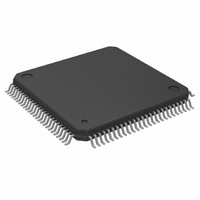
IC CTRLR SUPER I/O MULTI 100-QFP
Manufacturer
SMSC
Datasheet
1.FDC37C665GT-MS.pdf
(152 pages)
Specifications of FDC37C665GT-MS
Controller Type
I/O Controller
Interface
ISA Host
Voltage - Supply
4.5 V ~ 5.5 V
Current - Supply
35mA
Operating Temperature
0°C ~ 70°C
Mounting Type
Surface Mount
Package / Case
100-QFP
Lead Free Status / RoHS Status
Lead free / RoHS Compliant
Other names
638-1007
Available stocks
Company
Part Number
Manufacturer
Quantity
Price
Company:

Part Number:
FDC37C665GT-MS
Manufacturer:
Microchip Technology
Quantity:
10 000


8.
9.
EPP 1.9 Read
The timing for a read operation (data) is shown
in timing diagram EPP Read Data cycle.
IOCHRDY is driven active low at the start of
each EPP read and is released when it has been
determined that the read cycle can complete.
The read cycle can complete under the following
circumstances:
1.If the EPP bus is not ready (nWAIT is active
2.If the EPP bus is ready (nWAIT is inactive
Read Sequence of Operation
1.
2.
3.
4.
5.
6.
7.
Peripheral asserts nWAIT, indicating to the
host that any hold time requirements have
been satisfied and acknowledging the
termination of the cycle.
Chip may modify nWRITE and nPDATA in
preparation for the next cycle.
low) when nDATASTB goes active then the
read can complete when nWAIT goes
inactive high.
high) then the chip must wait for it to go
active low before changing the state of
WRITE or before nDATASTB goes active.
The read can complete once nWAIT is
determined inactive.
The host selects an EPP register and drives
nIOR active.
The chip drives IOCHRDY inactive (low).
If WAIT is not asserted, the chip must wait
until WAIT is asserted.
The chip tri-states the PData bus and
deasserts nWRITE.
Chip asserts nDATASTB or nADDRSTRB
indicating that PData bus is tri-stated, PDIR
is set and the nWRITE signal is valid.
Peripheral drives PData bus valid.
Peripheral deasserts nWAIT, indicating that
PData is valid and the chip may begin the
termination phase of the cycle.
97
8.
9.
10. Chip may modify nWRITE, PDIR
EPP 1.7 OPERATION
When the EPP 1.7 mode is selected in the
configuration register, the standard and bi-
directional modes are also available. If no EPP
Read, Write or Address cycle is currently
executing, then the PDx bus is in the standard or
bi-directional mode, and all output signals
(STROBE, AUTOFD, INIT) are as set by the
SPP Control Port and direction is controlled by
PCD of the Control port.
In EPP mode, the system timing is closely
coupled to the EPP timing. For this reason, a
watchdog timer is required to prevent system
lockup. The timer indicates if more than 10usec
have elapsed from the start of the EPP cycle
(nIOR or nIOW asserted) to the end of the cycle
nIOR or nIOW deasserted).
occurs, the current EPP cycle is aborted and the
time-out condition is indicated in Status bit 0.
Software Constraints
Before an EPP cycle is executed, the software
must ensure that the control register bits D0, D1
and D3 are set to zero. Also, bit D5 (PCD) is a
logic "0" for an EPP write or a logic "1" for and
EPP read.
a)
b)
Peripheral tri-states the PData bus and
asserts nWAIT, indicating to the host that
the PData bus is tri-stated.
nPDATA in preparation for the next cycle.
The chip latches the data from the
PData
deasserts nDATASTB or nADDRSTRB,
this
termination phase.
The chip drives the valid data onto the
SData bus and asserts (releases)
IOCHRDY
complete the read cycle.
marks
bus
allowing
the
for
beginning
the
the
If a time-out
SData
host
of
bus,
and
the
to
Related parts for FDC37C665GT-MS
Image
Part Number
Description
Manufacturer
Datasheet
Request
R

Part Number:
Description:
FAST ETHERNET PHYSICAL LAYER DEVICE
Manufacturer:
SMSC Corporation
Datasheet:
Part Number:
Description:
357-036-542-201 CARDEDGE 36POS DL .156 BLK LOPRO
Manufacturer:
SMSC Corporation
Datasheet:
Part Number:
Description:
357-036-542-201 CARDEDGE 36POS DL .156 BLK LOPRO
Manufacturer:
SMSC Corporation
Datasheet:
Part Number:
Description:
357-036-542-201 CARDEDGE 36POS DL .156 BLK LOPRO
Manufacturer:
SMSC Corporation
Datasheet:
Part Number:
Description:
4-PORT USB2.0 HUB CONTROLLER
Manufacturer:
SMSC Corporation
Datasheet:
Part Number:
Description:
Manufacturer:
SMSC Corporation
Datasheet:
Part Number:
Description:
Manufacturer:
SMSC Corporation
Datasheet:
Part Number:
Description:
FDC37C672ENHANCED SUPER I/O CONTROLLER WITH FAST IR
Manufacturer:
SMSC Corporation
Datasheet:
Part Number:
Description:
COM90C66LJPARCNET Controller/Transceiver with AT Interface and On-Chip RAM
Manufacturer:
SMSC Corporation
Datasheet:
Part Number:
Description:
Manufacturer:
SMSC Corporation
Datasheet:
Part Number:
Description:
Manufacturer:
SMSC Corporation
Datasheet:
Part Number:
Description:
Manufacturer:
SMSC Corporation
Datasheet:
Part Number:
Description:
Manufacturer:
SMSC Corporation
Datasheet: