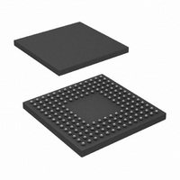
DP83815DUJB/NOPB National Semiconductor, DP83815DUJB/NOPB Datasheet - Page 20

DP83815DUJB/NOPB
Manufacturer Part Number
DP83815DUJB/NOPB
Description
IC MEDIA ACCESS CONTROL 160-LBGA
Manufacturer
National Semiconductor
Datasheet
1.DP83815DVNGNOPB.pdf
(108 pages)
Specifications of DP83815DUJB/NOPB
Controller Type
Ethernet Controller, MAC/BIU
Interface
PCI
Voltage - Supply
3.3V
Current - Supply
170mA
Operating Temperature
0°C ~ 70°C
Mounting Type
Surface Mount
Package / Case
160-LBGA
Lead Free Status / RoHS Status
Lead free / RoHS Compliant
Other names
*DP83815DUJB
*DP83815DUJB/NOPB
DP83815DUJB
*DP83815DUJB/NOPB
DP83815DUJB
Available stocks
Company
Part Number
Manufacturer
Quantity
Price
Company:
Part Number:
DP83815DUJB/NOPB
Manufacturer:
Texas Instruments
Quantity:
10 000
Subject to change without notice.
3.0 Functional Description
3.6 Half Duplex vs. Full Duplex
The DP83815 supports both half and full duplex operation
at both 10 Mb/s and 100 Mb/s speeds.
Half-duplex is the standard, traditional mode of operation
which relies on the CSMA/CD protocol to handle collisions
and network access. In Half-Duplex mode, CRS responds
to both transmit and receive activity in order to maintain
compliance with IEEE 802.3 specification.
Since the DP83815 is designed to support simultaneous
transmit and receive activity it is capable of supporting full-
duplex switched applications with a throughput of up to 200
Mb/s per port when operating in 100BASE-TX mode.
Because the CSMA/CD protocol does not apply to full-
duplex operation, the DP83815 disables its own internal
collision sensing and reporting functions.
It is important to understand that while full Auto-Negotiation
with the use of Fast Link Pulse code words can interpret
and configure to support full-duplex, parallel detection can
not recognize the difference between full and half-duplex
from a fixed 10 Mb/s or 100 Mb/s link partner over twisted
pair. Therefore, as specified in 802.3u, if a far-end link
partner is transmitting forced full duplex 100BASE-TX for
example, the parallel detection state machine in the
receiving station would be unable to detect the full duplex
capability of the far-end link partner and would negotiate to
a half duplex 100BASE-TX configuration (same scenario
for 10 Mb/s).
For full duplex operation, the following register bits must
also be set:
— TXCFG:CSI (Carrier Sense Ignore)
— TXCFG:HBI (HeartBeat Ignore)
— RXCFG:ATX (Accept Transmit Packets)
Additionally, the Auto-Negotiation Select bits in the
Configuration register must show full duplex support:
— CFG:ANEG_SEL
3.7 Phy Loopback
The DP83815 includes a Phy Loopback Test mode for
easy board diagnostics. The Loopback mode is selected
through bit 14 (Loopback) of the Basic Mode Control
Register (BMCR). Writing 1 to this bit enables transmit data
to be routed to the receive path early in the physical layer
cell. Loopback status may be checked in bit 3 of the PHY
Status Register (C0h). While in Loopback mode the data
will not be transmitted onto the media. This is true for either
10 Mb/s as well as 100 Mb/s data.
(Continued)
20
In 100BASE-TX Loopback mode the data is routed through
the PCS and PMA layers into the PMD sublayer before it is
looped back. Therefore, in addition to serving as a board
diagnostic, this mode serves as quick functional verification
of the device.
Note: A Mac Loopback can be performed via setting bit 29
(Mac Loopback) in the Tx Configuration Register.
3.8 Status Information
There are 3 pins that are available to convey status
information to the user through LEDs to indicate the speed
(10 Mb/s or 100 Mb/s) link status and receive or transmit
activity.
10 Mb/s Link is established as a result of the reception of at
least seven consecutive Normal Link Pulses or the
reception of a valid 10BASE-T packet. LED10N will de-
assert in accordance with the Link Loss Timer specified in
IEEE 802.3.
100BASE-T Link is established as a result of an input
receive amplitude compliant with TP-PMD specifications
which will result in internal generation of Signal Detect.
LED100N will assert after the internal Signal Detect has
remained asserted for a minimum of 500 µs. LED100N will
de-assert immediately following the de-assertion of the
internal Signal Detect.
Activity LED status indicates Receive or Transmit activity.
3.9 100BASE-TX TRANSMITTER
The 100BASE-TX transmitter consists of several functional
blocks which convert synchronous 4-bit nibble data, to a
scrambled MLT-3 125 Mb/s serial data stream. Because
the 100BASE-TX TP-PMD is integrated, the differential
output pins, TD±, can be directly routed to the magnetics.
The block diagram in Figure 3-6 provides an overview of
each functional block within the 100BASE-TX transmit
section.
The Transmitter section consists of the following functional
blocks:
— Code-group Encoder and Injection block (bypass option)
— Scrambler block (bypass option)
— NRZ to NRZI encoder block
— Binary to MLT-3 converter / Common Driver
The bypass option for the functional blocks within the
100BASE-TX transmitter provides flexibility for applications
such as 100 Mb/s repeaters where data conversion is not
always required. The DP83815 implements the 100BASE-
TX transmit state machine diagram as specified in the
IEEE 802.3u Standard, Clause 24.
Rev O
www.national.com


