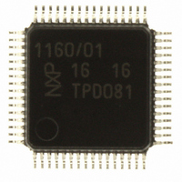
ISP1160BM01TM ST-Ericsson Inc, ISP1160BM01TM Datasheet - Page 11

ISP1160BM01TM
Manufacturer Part Number
ISP1160BM01TM
Description
IC USB HOST CTRL FULL-SPD 64LQFP
Manufacturer
ST-Ericsson Inc
Datasheet
1.ISP1160BM01FE.pdf
(89 pages)
Specifications of ISP1160BM01TM
Controller Type
USB 2.0 Controller
Interface
Parallel
Voltage - Supply
3.3V, 5V
Current - Supply
47mA
Operating Temperature
-40°C ~ 85°C
Mounting Type
Surface Mount
Package / Case
64-LQFP
Lead Free Status / RoHS Status
Lead free / RoHS Compliant
Other names
568-1879-2
ISP1160BM/01,118
ISP1160BM01-T
ISP1160BM/01,118
ISP1160BM01-T
Available stocks
Company
Part Number
Manufacturer
Quantity
Price
Company:
Part Number:
ISP1160BM01TM
Manufacturer:
ST-Ericsson Inc
Quantity:
10 000
Philips Semiconductors
9397 750 13963
Product data
8.3.1 I/O port addressing
8.3.2 Register access phases
8.3 Control registers access by PIO mode
Table 3
address should include the chip select signal CS_N and the address line A0.
However, the direction of access of I/O ports is controlled by the RD_N and
WR_N signals. When RD_N is LOW, the microprocessor reads data from the
ISP1160’s data port. When WR_N is LOW, the microprocessor writes a command to
the command port, or writes data to the data port.
Table 3:
Figure 5
control registers.
The ISP1160’s register structure is a command-data register pair structure. A
complete register access cycle comprises a command phase followed by a data
phase. The command (also known as the index of a register) points the ISP1160 to
the next register to be accessed. A command is 8 bits long. On a microprocessor’s
16-bit data bus, a command occupies the lower byte, with the upper byte filled with
zeros.
Figure 6
microprocessor writes a command code to the command port, and then reads from or
writes the data word to the data port. Take the example of a microprocessor
attempting to read the ISP1160’s ID, which is saved in the HC’s HcChipID register
(index 27H, read only). The 16-bit register access cycle is therefore:
Port
0
1
1. The microprocessor writes the command code of 27H (0027H in 16-bit width) to
2. The microprocessor reads the data word of the chip’s ID from the HC data port.
Fig 5. Access to internal control registers.
the HC command port
When A0
When A0
shows the ISP1160’s I/O port addressing. Complete decoding of the I/O port
illustrates how an external microprocessor accesses the ISP1160’s internal
shows a complete 16-bit register access cycle for the ISP1160. The
CS_N
0
0
I/O port addressing
0, microprocessor accesses the data port.
1, microprocessor accesses the command port.
Rev. 05 — 24 December 2004
Host bus I/F
A0
0
1
A0
CMD/DATA
Access Data bus width
R/W
W
SWITCH
1
0
(bits)
16
16
command port
data port
Control registers
. .
.
Embedded USB Host Controller
Description
HC data port
HC command port
© Koninklijke Philips Electronics N.V. 2004. All rights reserved.
Command register
Commands
004aaa075
ISP1160
10 of 88


