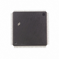
DP83950BVQB National Semiconductor, DP83950BVQB Datasheet - Page 24

DP83950BVQB
Manufacturer Part Number
DP83950BVQB
Description
IC CTRLR RIC REPEATER 160-PQFP
Manufacturer
National Semiconductor
Datasheet
1.DP83950BVQB.pdf
(80 pages)
Specifications of DP83950BVQB
Controller Type
Ethernet Repeater Interface Controller
Interface
IEEE 802.3
Voltage - Supply
4.75 V ~ 5.25 V
Current - Supply
380mA
Operating Temperature
0°C ~ 70°C
Mounting Type
Surface Mount
Package / Case
160-MQFP, 160-PQFP
Lead Free Status / RoHS Status
Contains lead / RoHS non-compliant
Other names
*DP83950BVQB
Available stocks
Company
Part Number
Manufacturer
Quantity
Price
Company:
Part Number:
DP83950BVQB
Manufacturer:
NS
Quantity:
43
Company:
Part Number:
DP83950BVQB
Manufacturer:
Texas Instruments
Quantity:
10 000
5 0 Functional Description
LED Interface and Hub Management Function
Repeater systems usually possess optical displays indicat-
ing network activity and the status of specific repeater oper-
ations The RIC’s display update block provides the system
designer with a wide variety of indicators The display up-
dates are completely autonomous and merely require SSI
logic devices to drive the display devices usually made up
of light emitting diodes LEDs The status display is very
flexible allowing the user to choose those indicators appro-
priate for the specification of the equipment
The RIC has been designed with special awareness for sys-
tem designers implementing large repeaters possessing
hub management capabilities Hub management uses the
unique position of repeaters in a network to gather statistics
about the network segments they are attached to The RIC
provides hub management statistical data in 3 steps Impor-
tant events are gathered by the management block from
logic blocks throughout the chip These events may then be
stored in on-chip latches or counted in on-chip counters ac-
cording to user supplied latching and counting masks
The fundamental task of a hub management system imple-
mentation is to associate the current packet and any man-
agement status information with the network segment i e
repeater port where the packet was received The ideal sys-
tem would place this combined data packet and status field
in system memory for examination by hub management
software The ultimate function of the RIC’s hub manage-
ment support logic is to provide this function
To accomplish this the RIC utilizes a dedicated hub man-
agement interface This is similar to the Inter-RIC bus since
it allows the data packet to be recovered from the receiving
RIC Unlike the Inter-RIC bus the intended recipient is not
another RIC but National Semiconductor’s DP83932
‘‘SONIC
allows a management status field to be appended at the
end of the data packet This can be done without affecting
the operation of the repeater system
Processor Interface
The RIC’s processor interface allows connection to a sys-
tem processor Data transfer occurs via an octal bi-direc-
tional data bus The RIC has a number of on-chip registers
indicating the status of the hub management functions chip
configuration and port status These may be accessed by
providing the chosen address at the Register Address
(RA4 –RA0) input pins
Display update cycles and processor accesses occur utiliz-
ing the same data bus An on-chip arbiter in the processor
display block schedules and controls the accesses and en-
sures the correct information is written into the display latch-
es During the display update cycles the RIC behaves as a
master of its data bus This is the default state of the data
bus Consequently a TRI-STATE buffer must be placed be-
tween the RIC and the system processor’s data bus This
TM
’’ Network controller The use of a dedicated bus
(Continued)
24
ensures bus contention is avoided during simultaneous dis-
play update cycles and processor accesses of other devic-
es on the system bus When the processor accesses a RIC
register the RIC enables the data buffer and selects the
operation either input or output of the data pins
5 2 DESCRIPTION OF REPEATER OPERATIONS
In order to implement a multi-chip repeater system which
behaves as though it were a single logical repeater special
consideration must be paid to the data path used in packet
repetition For example where in the path are specific oper-
ations such as Manchester decoding and elasticity buffering
performed Also the system’s state machines which utilize
available network activity signals must be able to accom-
modate the various packet repetition and collision scenarios
detailed in the repeater specification
The RIC contains two types of inter-acting state machines
These are
1 Port State Machines (PSMs) Every network attachment
2 Main State Machine (MSM) This state machine controls
Repeater Port and Main State Machines
These two state machines are described in the following
sections Reference is made to expressions used in the
IEEE Repeater specification For the precise definition of
these terms please refer to the specification To avoid con-
fusion with the RIC’s implementation where references are
made to repeater states or terms as described in the IEEE
specification these items are written in italics The IEEE
state diagram is shown in Figure 5-3 the Inter-RIC bus state
diagram is shown in Figure 5-2
has its own PSM
the shared functional blocks as shown in the block dia-
gram Figure 5 1
FIGURE 5 2 Inter-RIC Bus State Diagram
TL F 11096 – 7


