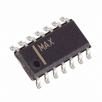
MAX13041ASD+ Maxim Integrated Products, MAX13041ASD+ Datasheet - Page 15

MAX13041ASD+
Manufacturer Part Number
MAX13041ASD+
Description
IC CAN TXRX +/-80V HS 14-SOIC
Manufacturer
Maxim Integrated Products
Type
Transceiverr
Datasheet
1.MAX13041ASD.pdf
(20 pages)
Specifications of MAX13041ASD+
Number Of Drivers/receivers
1/1
Protocol
CAN
Voltage - Supply
4.75 V ~ 5.25 V
Mounting Type
Surface Mount
Package / Case
14-SOIC (3.9mm Width), 14-SOL
Lead Free Status / RoHS Status
Lead free / RoHS Compliant
normal mode, prior to the fourth dominant-to-recessive
transition on TXD. A low level on ERR indicates a local
wake-up has occurred.
The bus failure flag is set when the MAX13041 detects
a CAN bus short-circuit to V
consecutive dominant-recessive cycles on TXD. The
flag is cleared when the MAX13041 leaves normal
mode. The bus failure flag is externally indicated as a
logic low on ERR in normal mode, after the fourth domi-
nant-to-recessive transition on TXD.
The local failure flag indicates five separate local failure
conditions (see Fault Protection & Fail-Safes section).
When one or more local failure conditions have
occurred, the local failure flag is set. The flag is cleared
when the MAX13041 enters normal mode or when RXD
goes logic-low while TXD is logic-high. The local failure
flag is externally indicated as a logic-low on ERR when
the MAX13041 is placed into PWON/listen-only mode
from normal mode.
The MAX13041 provides wake-on-CAN capability from
sleep mode. When the MAX13041 detects two domi-
nant bus states, each followed by a recessive state
(Figure 5), the MAX13041 sets the wake-up flag and
enters an operating mode determined by the state of
EN and STB. Each CAN logic state must be at least 5µs
in duration. This wake-up detection criterion serves to
prevent unintentional wake-up events due to bus faults
such as V
higher data rates (>125kbit/s), wake-up can not be
guaranteed for a single, arbitrary CAN data frame. Two
or more consecutive arbitrary CAN data frames may be
required to ensure a successful wake-on-CAN event.
MAX13041 controls one or more external voltage regu-
lators through INH, a V
put. When INH is logic-high, any external voltage
regulators are active and power is supplied to the
node. When INH is high-impedance, the typical pull-
down characteristic of the voltage-regulator inhibit input
pulls INH to a logic-low and disables the external volt-
age regulator(s).
The MAX13041 features ±80V tolerance on CAN bus
lines CANH, CANL, and SPLIT. Up to +76V operation is
possible on V
applications. Additionally, the device detects local and
remote bus failures and features fail-safe modes to
±80V Fault-Protected High-Speed CAN Transceiver
with Low-Power Management and Wake-On CAN
BAT
External-Voltage Regulator Control
BAT
to CANH or an open circuit on CANL. At
, allowing for use in +42V automotive
______________________________________________________________________________________
Fault Protection & Fail-Safes
BAT
-referenced, open-drain out-
BAT
, V
CC,
Local Failure Flag
Wake-On CAN
Bus Failure Flag
or GND for four
prevent damage to the device or interference with CAN
bus communication.
The MAX13041 detects five different local faults. When
any local fault is detected, the local failure flag is set.
Additionally, for faults other than bus dominant clamp-
ing, the transmitter is disabled to prevent possible dam-
age to the device. The transmitter remains disabled
until the local failure flag is cleared.
An extended logic-low level on TXD due to hardware or
software failure would ordinarily clamp the CAN bus to
a dominant state, blocking communication on the entire
bus. This condition is prevented by the TXD dominant
time-out feature. If TXD is held low for longer than
t
ter is disabled until the local failure flag is cleared. The
TXD time-out value limits the minimum allowable bit rate
to 40kbps.
If a hardware failure clamps RXD to a logic-high level,
the protocol controller assumes the CAN bus is in a
recessive state at all times. This has the undesirable
effect that the protocol controller assumes the bus is
clear and may initiate messages that would interfere with
ordinary communication. This local failure is detected by
checking the state of RXD when the CAN bus is in a
dominant state. If RXD does not reflect the state of the
CAN bus, the local failure flag is set and the transmitter is
disabled until the local failure flag is cleared.
A short-circuit between TXD and RXD forces the bus
into a permanent dominant state upon the first transmis-
sion of a dominant bit because normally the low-side
driver of RXD is stronger than the microcontroller high-
side driver of TXD. The MAX13041 detects this condi-
tion and prevents the resulting bus failure by setting the
local failure flag and disabling the transmitter. The
transmitter remains disabled until the local failure flag is
cleared.
A short-circuit fault from the CAN bus to V
GND could produce a differential voltage between
CANH and CANL greater than the receiver threshold,
resulting in a dominant bus state. If the bus state is
clamped dominant for longer than t
failure flag is set. The transmitter is not disabled by this
fault and the local failure flag is cleared as soon as the
bus state becomes recessive.
DOM(TXD)
, the local failure flag is set and the transmit-
TXD-to-RXD Short-Circuit Detection
RXD Recessive Clamping
TXD Dominant Clamping
Bus Dominant Clamping
DOM(BUS)
BAT
, the local
, V
CC
, or
15


