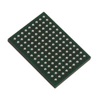
VSC8211XVW Vitesse Semiconductor Corp, VSC8211XVW Datasheet - Page 107

VSC8211XVW
Manufacturer Part Number
VSC8211XVW
Description
IC PHY 10/100/1000 SGL 117-LBGA
Manufacturer
Vitesse Semiconductor Corp
Type
PHY Transceiverr
Specifications of VSC8211XVW
Number Of Drivers/receivers
1/1
Protocol
Gigabit Ethernet
Voltage - Supply
3 V ~ 3.6 V
Mounting Type
Surface Mount
Package / Case
117-LBGA
Case
BGA
Dc
07+
Lead Free Status / RoHS Status
Lead free / RoHS Compliant
Other names
907-1023
Available stocks
Company
Part Number
Manufacturer
Quantity
Price
Company:
Part Number:
VSC8211XVW
Manufacturer:
VITESSE
Quantity:
5
Company:
Part Number:
VSC8211XVW
Manufacturer:
Semtech
Quantity:
3 413
Company:
Part Number:
VSC8211XVW
Manufacturer:
VITESSE
Quantity:
648
Company:
Part Number:
VSC8211XVW
Manufacturer:
Vitesse Semiconductor Corporation
Quantity:
10 000
Part Number:
VSC8211XVW
Manufacturer:
VITESSE
Quantity:
20 000
22.11:10 – 10BASE-T Squelch Control
When bits 22.11:10 are set to “00”, the VSC8211 uses the squelch threshold levels prescribed by the IEEE’s 10BASE-T
specification. When bits 22.11:10 are set to “01”, the squelch level is decreased, which may improve the bit error rate
performance on long loops. When bits 22.11:10 are set to “10”, the squelch level is increased, which may improve the bit error
rate in high-noise environments.
22.9 - Sticky Reset Enable
When bit 22.9 is set, all MII register bits that are marked with an “S” in the “sticky” column will retain their values during a
software reset. When cleared, all MII register bits that are marked with an “S” in the “sticky” column will be changed to their
default values during a software reset. Note that bits marked with an “SS” retain their values across software reset regardless of
the setting of bit 22.9.
22.8 – EOF Error
When bit 22.8 returns a “1”, a defective EOF (End-of-Frame) sequence has been received since the last time this bit was read.
This bit is automatically set to “0” when it is read.
22.7 – 10BASE-T Disconnect State
Bit 22.7 is set to “1” if the 10BASE-T connection has been broken by the carrier integrity monitor since the last read of this bit;
otherwise, this bit is set to “0”.
22.6 – 10BASE-T Link Status
Bit 22.6 is set to “1” if the 10BASE-T link is active. Otherwise, this bit is set to “0”.
22.5:3 – Reserved
22.2:1 - CRS Control
Bits 22.2:1 determine the behavior of the CRS indication provided by the VSC8211 according to the following table:
22.0 – Reserved
1
VMDS-10105 Revision 4.1
October 2006
This bit applies only in 10BASE-T mode.
1000BASE-T
Full-Duplex
1000BASE-T
Half-Duplex
100BASE-TX
Full-Duplex
100BASE-TX
Half-Duplex
10BASE-T
Full-Duplex
10BASE-T
Half-Duplex
1
00 (default)
CRS = RXDV
CRS = Logical OR of RXDV and TXEN CRS = Logical OR of RXDV and TXEN CRS = RXDV CRS = RXDV
CRS = RXDV
CRS = Logical OR of RXDV and TXEN CRS = Logical OR of RXDV and TXEN CRS = RXDV CRS = RXDV
CRS = RXDV
CRS = Logical OR of RXDV and TXEN CRS = Logical OR of RXDV and TXEN CRS = RXDV CRS = RXDV
1
107 of 165
CRS Control Bits - bits 2:1
01
CRS = 0
CRS = 0
CRS = 0
10
CRS = RXDV CRS = 0
CRS = RXDV CRS = 0
CRS = RXDV CRS = 0
11
Datasheet
VSC8211


