VSC8211XVW Vitesse Semiconductor Corp, VSC8211XVW Datasheet - Page 45
VSC8211XVW
Manufacturer Part Number
VSC8211XVW
Description
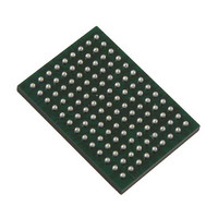
IC PHY 10/100/1000 SGL 117-LBGA
Manufacturer
Vitesse Semiconductor Corp
Type
PHY Transceiverr
Specifications of VSC8211XVW
Number Of Drivers/receivers
1/1
Protocol
Gigabit Ethernet
Voltage - Supply
3 V ~ 3.6 V
Mounting Type
Surface Mount
Package / Case
117-LBGA
Case
BGA
Dc
07+
Lead Free Status / RoHS Status
Lead free / RoHS Compliant
Other names
907-1023
Available stocks
Company
Part Number
Manufacturer
Quantity
Price
Company:

Part Number:
VSC8211XVW
Manufacturer:
VITESSE
Quantity:
5
Company:
Part Number:
VSC8211XVW
Manufacturer:
Semtech
Quantity:
3 413
Company:
Part Number:
VSC8211XVW
Manufacturer:
VITESSE
Quantity:
648
Company:
Part Number:
VSC8211XVW
Manufacturer:
Vitesse Semiconductor Corporation
Quantity:
10 000
Part Number:
VSC8211XVW
Manufacturer:
VITESSE
Quantity:
20 000


•
•
•
•
•
•
•
•
11.4 Twisted Pair Link Speed Downshift
In addition to automatic crossover detection, the VSC8211 supports an automatic link speed “downshift” option for operation in
cabling environments incompatible with 1000BASE-T. When this feature is enabled, the VSC8211 will automatically change its
autonegotiation advertisement to 100BASE-TX after a set number of failed attempts at 1000BASE-T. This is especially useful in
setting up networks using older cable installations which may include only pairs A and B and not pairs C and D. The link speed
downshift feature is configured and monitored using
11.5 100Mbps Fiber Support Over Copper Media Interface
The VSC8211 supports 100BASE-FX over its copper media interface by using pairs A and B, which provide TX and RX
differential connections, respectively. If the fiber module does not have internal AC coupling capacitors, then they are required
between the PHY and fiber module. The value should be 0.1µF.
The RXLOS/SIGDET signal is not used in this mode.
A separate 1000BASE-X fiber module may be connected to the PHY through the 1000BASE-X SerDes pins.
11.5.1 Register Settings
The PHY can be brought into the 100BASE-FX operation mode using the following configuring sequence:
12 Transformerless Operation for PICMG 2.16 and 3.0 IP-based Backplanes
The twisted pair interface supports capacitively coupled links, such as those specified by the PICMG 2.16 and 3.0
specifications. With proper AC coupling, the typical category-5 magnetic isolation can be replaced with capacitors. For more
information, see
Ethernet Concept and Applications”.
By enabling the PICMG Miser mode, power consumption can be reduced to approximately 500mW.
13 Dual Mode Serial Management Interface (SMI)
The Serial Management Interface provides access to the PHY registers for device configuration and Status Information. It also
provides access to the EEPROM connected to the EEDAT and EECLK pins (EEPROM Interface) of the PHY. For details on
EEPROM access through the SMI interface refer to
VMDS-10105 Revision 4.1
October 2006
Write MII Register 8 = 0x0212
Write MII Register 31 = 0x52B5
Write MII Register 2 = 0x0012
Write MII Register 1 = 0x3003
Write MII Register 0 = 0x87FA
Write MII Register 31 = 0x2A30
Write MII Register 8 = 0x0012
Write MII Register 31 = 0x0000
1.
2.
3.
4.
Initialize the PHY into the specific MAC-to-copper operating mode for the MAC interface type required (register 23).
Disable Auto-Negotiation and force the 100BASE-T FDX mode (register 0).
Run the 100BASE-FX initialization script; for more information, see
Configure other settings, such as LEDs.
“Register 24 (18h) – PHY Control Register #2,”
Section 20: "EEPROM
Register 20E (14h) - Extended PHY Control Register #3.
45 of 165
page 111, and the Vitesse application note “Transformerless
Interface".
Section 33.4: "100BASE-FX Initialization
Datasheet
VSC8211
Script".
Related parts for VSC8211XVW
Image
Part Number
Description
Manufacturer
Datasheet
Request
R

Part Number:
Description:
Single Port 10/100/1000base-t Phy And 1000base-x Phy With Sgmii, Serdes, Gmii, Mii, Tbi, Rgmii / Rtbi Mac Interfaces Semiconductor Corporation
Manufacturer:
Vitesse Semiconductor Corp
Datasheet:
Part Number:
Description:
Multi-rate 16 1 Sonet/sdh Transceiver With Integrated Clock Generator Semiconductor Corporation
Manufacturer:
Vitesse Semiconductor Corp
Datasheet:
Part Number:
Description:
2.488gb/s 4 1 Sonet/sdh Transceiver With Integrated Clock Generator Semiconductor Corporation
Manufacturer:
Vitesse Semiconductor Corp
Datasheet:
Part Number:
Description:
2.488 Gbit/sec To 2.7gbit/sec 1 16 Sonet/sdh Demux Semiconductor Corporation
Manufacturer:
Vitesse Semiconductor Corp
Datasheet:
Part Number:
Description:
10.3125 Gbps Advanced Electronic Equalization With Limiting Amplifier, And Clock And Data Recovery Semiconductor Corporation
Manufacturer:
Vitesse Semiconductor Corp
Datasheet:
Part Number:
Description:
34x34 Crosspoint Switch With Signal Detection Semiconductor Corporation
Manufacturer:
Vitesse Semiconductor Corp
Datasheet:
Part Number:
Description:
10 Gbps Queue Manager With Integrated Spi4.2 Interface Semiconductor Corporation
Manufacturer:
Vitesse Semiconductor Corp
Datasheet:
Part Number:
Description:
High Performance 16x16 Serial Crosspoint Switch Semiconductor Corporation
Manufacturer:
Vitesse Semiconductor Corp
Datasheet:
Part Number:
Description:
16-port Jbod Loop Chip For 1.0625 Gb/s Fc-al Storage Applications Semiconductor Corporation
Manufacturer:
Vitesse Semiconductor Corp
Datasheet:
Part Number:
Description:
Quad Port Bypass Circuit Semiconductor Corporation
Manufacturer:
Vitesse Semiconductor Corp
Datasheet:

Part Number:
Description:
IC PHY 10/100/1000 64-EP-LQFP
Manufacturer:
Vitesse Semiconductor Corp
Datasheet:

Part Number:
Description:
IC PHY 10/100/1000 260-HS-PBGA
Manufacturer:
Vitesse Semiconductor Corp
Datasheet:

Part Number:
Description:
IC PHY 10/100/1000 444-HS-BGA
Manufacturer:
Vitesse Semiconductor Corp
Datasheet:

Part Number:
Description:
IC TXRX MULTIRATE 16BIT 208-BGA
Manufacturer:
Vitesse Semiconductor Corp
Datasheet:
Part Number:
Description:
TRANSCEIVER SRL XAUI XGMII I/O
Manufacturer:
Vitesse Semiconductor Corp