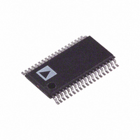
ADM2209EARU Analog Devices Inc, ADM2209EARU Datasheet - Page 11

ADM2209EARU
Manufacturer Part Number
ADM2209EARU
Description
IC TXRX6/10 RS-232 12V 38TSSOP
Manufacturer
Analog Devices Inc
Type
Transceiverr
Datasheet
1.ADM2209EARUZ.pdf
(12 pages)
Specifications of ADM2209EARU
Rohs Status
RoHS non-compliant
Number Of Drivers/receivers
6/10
Protocol
RS232
Voltage - Supply
10.8 V ~ 13.2 V
Mounting Type
Surface Mount
Package / Case
38-TSSOP
Available stocks
Company
Part Number
Manufacturer
Quantity
Price
Part Number:
ADM2209EARU
Manufacturer:
ADI/亚德诺
Quantity:
20 000
Part Number:
ADM2209EARUD
Manufacturer:
ADI/亚德诺
Quantity:
20 000
Part Number:
ADM2209EARUZ
Manufacturer:
ADI/亚德诺
Quantity:
20 000
Company:
Part Number:
ADM2209EARUZ-REEL7
Manufacturer:
BROADCOM
Quantity:
145
Part Number:
ADM2209EARUZ-REEL7
Manufacturer:
ADI/亚德诺
Quantity:
20 000
REV. 0
Testing for immunity involves irradiating the device with an EM
field. There are various methods of achieving this, including use
of an echoic chamber, stripline cell, TEM cell, GTEM cell. A
stripline cell consists of two parallel plates with an electric field
developed between them. The device under test is placed within
the cell and exposed to the electric field. There are three severity
levels having field strengths ranging from 1 V to 10 V/m. Results
are classified in a fashion similar to those for IEC1000-4-4.
1. Normal operation.
2. Temporary degradation or loss of function that is self-
3. Temporary degradation or loss of function that requires
4. Degradation or loss of function that is not recoverable due to
The ADM2209E easily meets Classification 1 at the most strin-
gent (Level 3) requirement. In fact, field strengths up to 30 V/m
showed no performance degradation and error-free data trans-
mission continued even during irradiation.
EMISSIONS/INTERFERENCE
EN55 022, CISPR22 defines the permitted limits of radiated
and conducted interference from Information Technology (IT)
equipment. The objective of the standard is to minimize the
level of emissions, both conducted and radiated.
APPLICATIONS INFORMATION
In a typical Data Terminal Equipment (DTE) to Data Circuit
Terminating Equipment (DCE) 9-lead de facto interface imple-
mentation, two data lines (TxD and RxD) and six control lines
(RTS, DTR, DSR, CTS and RI) are required. With its six
drivers and ten receivers, the ADM2209E offers a single-chip
solution for the two RS-232 ports normally supplied as standard
in a desktop or notebook personal computer, as shown in Figure
28. The flow-through pinout of the device allows for a very
simple PCB layout, and allows a ground plane to be placed
beneath the IC, and ground lines to be inserted between the
recoverable when the interfering signal is removed.
operator intervention or system reset when the interfering
signal is removed.
damage.
Table VII. Test Severity Levels (IEC1000-4-3)
Level
1
2
3
Field Strength
V/m
1
3
10
–11–
signal lines to minimize crosstalk, without the complication of
multilayer PCBs.
Note that the two receivers kept active by the standby supply
(R5
line, so that the system can be awakened when a peripheral
device begins to communicate.
FAIL-SAFE RECEIVER OUTPUTS
The ADM2209E has fail-safe receiver outputs that assume a
high output level if the receiver input is zero or open-circuit.
LAPLINK COMPATIBILITY
The ADM2209E can operate up to 460 kbps data rate under
maximum driver load conditions of C
R
L
SUPER I/O
+12V
= 3 k at minimum power supply voltages.
IN
Figure 28. Typical Application for a Dual Serial Port
CHIP
A and R5
0.1 F
0.1 F
IN
DCD
DSR
RxD
RTS
CTS
DTR
DCD
DSR
RxD
RTS
CTS
DTR
TxD
TxD
RI
RI
B) should be connected to the Ring In (RI)
ADM2209E
R2
R3
R4
R5
R2
R3
R4
R5
R1
T1
T2
T3
R1
T1
T2
T3
+3V or +5V
0.1 F
L
DCD
DSR
DCD
DSR
RxD
RTS
CTS
DTR
RxD
RTS
CTS
DTR
TxD
TxD
RI
RI
= 1000 pF and
0.1 F
ADM2209E
6
7
8
9
6
7
8
9
1
3
4
1
3
4
5
2
5
2
9-WAY D
CONNECTOR
COM2
9-WAY D
CONNECTOR
COM1


