A000003 Arduino, A000003 Datasheet - Page 119
A000003
Manufacturer Part Number
A000003
Description
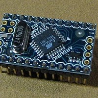
MCU, MPU & DSP Development Tools MINI
Manufacturer
Arduino
Series
-r
Type
MCUr
Specifications of A000003
Processor To Be Evaluated
Atmega328
Processor Series
ATmega
Data Bus Width
8 bit
Interface Type
USB, RS-232
Operating Supply Voltage
7 V to 9 V
Contents
Board
Lead Free Status / Rohs Status
Lead free / RoHS Compliant
For Use With/related Products
ATmega168


15.9
15.9.1
15.9.2
2545S–AVR–07/10
Modes of Operation
Normal Mode
Clear Timer on Compare Match (CTC) Mode
non-PWM modes refer to
page
page
A change of the COM1x1:0 bits state will have effect at the first compare match after the bits are
written. For non-PWM modes, the action can be forced to have immediate effect by using the
FOC1x strobe bits.
The mode of operation, that is, the behavior of the Timer/Counter and the Output Compare pins,
is defined by the combination of the Waveform Generation mode (WGM13:0) and Compare Out-
put mode (COM1x1:0) bits. The Compare Output mode bits do not affect the counting sequence,
while the Waveform Generation mode bits do. The COM1x1:0 bits control whether the PWM out-
put generated should be inverted or not (inverted or non-inverted PWM). For non-PWM modes
the COM1x1:0 bits control whether the output should be set, cleared or toggle at a compare
match
For detailed timing information refer to
The simplest mode of operation is the Normal mode (WGM13:0 = 0). In this mode the counting
direction is always up (incrementing), and no counter clear is performed. The counter simply
overruns when it passes its maximum 16-bit value (MAX = 0xFFFF) and then restarts from the
BOTTOM (0x0000). In normal operation the Timer/Counter Overflow Flag (TOV1) will be set in
the same timer clock cycle as the TCNT1 becomes zero. The TOV1 Flag in this case behaves
like a 17th bit, except that it is only set, not cleared. However, combined with the timer overflow
interrupt that automatically clears the TOV1 Flag, the timer resolution can be increased by soft-
ware. There are no special cases to consider in the Normal mode, a new counter value can be
written anytime.
The Input Capture unit is easy to use in Normal mode. However, observe that the maximum
interval between the external events must not exceed the resolution of the counter. If the interval
between events are too long, the timer overflow interrupt or the prescaler must be used to
extend the resolution for the capture unit.
The Output Compare units can be used to generate interrupts at some given time. Using the
Output Compare to generate waveforms in Normal mode is not recommended, since this will
occupy too much of the CPU time.
In Clear Timer on Compare or CTC mode (WGM13:0 = 4 or 12), the OCR1A or ICR1 Register
are used to manipulate the counter resolution. In CTC mode the counter is cleared to zero when
the counter value (TCNT1) matches either the OCR1A (WGM13:0 = 4) or the ICR1 (WGM13:0 =
12). The OCR1A or ICR1 define the top value for the counter, hence also its resolution. This
mode allows greater control of the compare match output frequency. It also simplifies the opera-
tion of counting external events.
The timing diagram for the CTC mode is shown in
increases until a compare match occurs with either OCR1A or ICR1, and then counter (TCNT1)
is cleared.
129, and for phase correct and phase and frequency correct PWM refer to
130.
(See “Compare Match Output Unit” on page
Table 15-1 on page
“Timer/Counter Timing Diagrams” on page
129. For fast PWM mode refer to
118.)
Figure
15-6. The counter value (TCNT1)
ATmega48/88/168
Table 15-2 on
Table 15-3 on
126.
119
Related parts for A000003
Image
Part Number
Description
Manufacturer
Datasheet
Request
R

Part Number:
Description:
Daughter Cards & OEM Boards ARDUINO UNO PROTO PCB REV 3
Manufacturer:
Arduino
Part Number:
Description:
Daughter Cards & OEM Boards ARDUINO SHIELD PROTO KIT REV 3
Manufacturer:
Arduino
Part Number:
Description:
Daughter Cards & OEM Boards ARDUINO MEGA PROTO KIT REV 3
Manufacturer:
Arduino
Part Number:
Description:
Daughter Cards & OEM Boards ARDUINO MEGA PROTO PCB REV 3
Manufacturer:
Arduino
Part Number:
Description:
Development Boards & Kits - AVR ARDUINO STARTER KIT W/ UNO REV3
Manufacturer:
Arduino
Part Number:
Description:
RF Development Tools ARDUINO SHIELD WIRELESS PROTO
Manufacturer:
Arduino
Datasheet:
Part Number:
Description:
RF Development Tools ARDUINO SHIELD WIRELESS WITH SD
Manufacturer:
Arduino
Datasheet:

Part Number:
Description:
Development Software Getting started w/Arduino
Manufacturer:
Arduino

Part Number:
Description:
Ethernet Modules & Development Tools Ethernet Shield for Arduino
Manufacturer:
Arduino

Part Number:
Description:
MCU, MPU & DSP Development Tools LilyPad Arduino Main Board
Manufacturer:
Arduino

Part Number:
Description:
ARDUINO NANO Board
Manufacturer:
Arduino
Datasheet:
Part Number:
Description:
Ethernet Modules & Development Tools ETHERNET SHEILD PoE FOR ARDUINO
Manufacturer:
Arduino
Datasheet:

Part Number:
Description:
ATMEGA328 MCU IC W/ Arduino UNO Bootloader
Manufacturer:
Arduino
Datasheet:
Part Number:
Description:
Memory Cards MICRO SD CARD 1GB WITH SD ADAPTER
Manufacturer:
Arduino