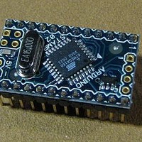
A000003 Arduino, A000003 Datasheet - Page 127

A000003
Manufacturer Part Number
A000003
Description
MCU, MPU & DSP Development Tools MINI
Manufacturer
Arduino
Series
-r
Type
MCUr
Specifications of A000003
Processor To Be Evaluated
Atmega328
Processor Series
ATmega
Data Bus Width
8 bit
Interface Type
USB, RS-232
Operating Supply Voltage
7 V to 9 V
Contents
Board
Lead Free Status / Rohs Status
Lead free / RoHS Compliant
For Use With/related Products
ATmega168
- Current page: 127 of 378
- Download datasheet (8Mb)
2545S–AVR–07/10
Figure 15-11. Timer/Counter Timing Diagram, Setting of OCF1x, with Prescaler (f
Figure 15-12
frequency correct PWM mode the OCR1x Register is updated at BOTTOM. The timing diagrams
will be the same, but TOP should be replaced by BOTTOM, TOP-1 by BOTTOM+1 and so on.
The same renaming applies for modes that set the TOV1 Flag at BOTTOM.
Figure 15-12. Timer/Counter Timing Diagram, no Prescaling
Figure 15-13
(PC and PFC PWM)
and ICFn
(CTC and FPWM)
TCNTn
OCRnx
OCFnx
(clk
TOVn
(Update at TOP)
clk
clk
I/O
TCNTn
TCNTn
OCRnx
as TOP)
(clk
I/O
Tn
clk
clk
/8)
I/O
shows the count sequence close to TOP in various modes. When using phase and
shows the same timing data, but with the prescaler enabled.
(FPWM)
I/O
Tn
/1)
(if used
OCRnx - 1
TOP - 1
TOP - 1
Old OCRnx Value
OCRnx
OCRnx Value
TOP
TOP
OCRnx + 1
ATmega48/88/168
BOTTOM
TOP - 1
New OCRnx Value
OCRnx + 2
BOTTOM + 1
TOP - 2
clk_I/O
/8)
127
Related parts for A000003
Image
Part Number
Description
Manufacturer
Datasheet
Request
R

Part Number:
Description:
Daughter Cards & OEM Boards ARDUINO UNO PROTO PCB REV 3
Manufacturer:
Arduino

Part Number:
Description:
Daughter Cards & OEM Boards ARDUINO SHIELD PROTO KIT REV 3
Manufacturer:
Arduino

Part Number:
Description:
Daughter Cards & OEM Boards ARDUINO MEGA PROTO KIT REV 3
Manufacturer:
Arduino

Part Number:
Description:
Daughter Cards & OEM Boards ARDUINO MEGA PROTO PCB REV 3
Manufacturer:
Arduino

Part Number:
Description:
Development Boards & Kits - AVR ARDUINO STARTER KIT W/ UNO REV3
Manufacturer:
Arduino

Part Number:
Description:
RF Development Tools ARDUINO SHIELD WIRELESS PROTO
Manufacturer:
Arduino
Datasheet:

Part Number:
Description:
RF Development Tools ARDUINO SHIELD WIRELESS WITH SD
Manufacturer:
Arduino
Datasheet:

Part Number:
Description:
Development Software Getting started w/Arduino
Manufacturer:
Arduino

Part Number:
Description:
Ethernet Modules & Development Tools Ethernet Shield for Arduino
Manufacturer:
Arduino

Part Number:
Description:
MCU, MPU & DSP Development Tools LilyPad Arduino Main Board
Manufacturer:
Arduino

Part Number:
Description:
ARDUINO NANO Board
Manufacturer:
Arduino
Datasheet:

Part Number:
Description:
Ethernet Modules & Development Tools ETHERNET SHEILD PoE FOR ARDUINO
Manufacturer:
Arduino
Datasheet:

Part Number:
Description:
ATMEGA328 MCU IC W/ Arduino UNO Bootloader
Manufacturer:
Arduino
Datasheet:

Part Number:
Description:
Memory Cards MICRO SD CARD 1GB WITH SD ADAPTER
Manufacturer:
Arduino


