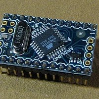
A000003 Arduino, A000003 Datasheet - Page 189
A000003
Manufacturer Part Number
A000003
Description
MCU, MPU & DSP Development Tools MINI
Manufacturer
Arduino
Series
-r
Type
MCUr
Specifications of A000003
Processor To Be Evaluated
Atmega328
Processor Series
ATmega
Data Bus Width
8 bit
Interface Type
USB, RS-232
Operating Supply Voltage
7 V to 9 V
Contents
Board
Lead Free Status / Rohs Status
Lead free / RoHS Compliant
For Use With/related Products
ATmega168


19.10 Register Description
19.10.1
19.10.2
2545S–AVR–07/10
UDRn – USART I/O Data Register n
UCSRnA – USART Control and Status Register n A
The USART Transmit Data Buffer Register and USART Receive Data Buffer Registers share the
same I/O address referred to as USART Data Register or UDRn. The Transmit Data Buffer Reg-
ister (TXB) will be the destination for data written to the UDRn Register location. Reading the
UDRn Register location will return the contents of the Receive Data Buffer Register (RXB).
For 5-bit, 6-bit, or 7-bit characters the upper unused bits will be ignored by the Transmitter and
set to zero by the Receiver.
The transmit buffer can only be written when the UDREn Flag in the UCSRnA Register is set.
Data written to UDRn when the UDREn Flag is not set, will be ignored by the USART Transmit-
ter. When data is written to the transmit buffer, and the Transmitter is enabled, the Transmitter
will load the data into the Transmit Shift Register when the Shift Register is empty. Then the
data will be serially transmitted on the TxDn pin.
The receive buffer consists of a two level FIFO. The FIFO will change its state whenever the
receive buffer is accessed. Due to this behavior of the receive buffer, do not use Read-Modify-
Write instructions (SBI and CBI) on this location. Be careful when using bit test instructions
(SBIC and SBIS), since these also will change the state of the FIFO.
• Bit 7 – RXCn: USART Receive Complete
This flag bit is set when there are unread data in the receive buffer and cleared when the receive
buffer is empty (that is, does not contain any unread data). If the Receiver is disabled, the
receive buffer will be flushed and consequently the RXCn bit will become zero. The RXCn Flag
can be used to generate a Receive Complete interrupt (see description of the RXCIEn bit).
• Bit 6 – TXCn: USART Transmit Complete
This flag bit is set when the entire frame in the Transmit Shift Register has been shifted out and
there are no new data currently present in the transmit buffer (UDRn). The TXCn Flag bit is auto-
matically cleared when a transmit complete interrupt is executed, or it can be cleared by writing
a one to its bit location. The TXCn Flag can generate a Transmit Complete interrupt (see
description of the TXCIEn bit).
• Bit 5 – UDREn: USART Data Register Empty
The UDREn Flag indicates if the transmit buffer (UDRn) is ready to receive new data. If UDREn
is one, the buffer is empty, and therefore ready to be written. The UDREn Flag can generate a
Data Register Empty interrupt (see description of the UDRIEn bit).
Bit
Read/Write
Initial Value
Bit
Read/Write
Initial Value
RXCn
R/W
7
0
R
7
0
R/W
TXCn
R/W
6
0
6
0
R/W
UDREn
5
0
R
5
1
R/W
4
0
FEn
RXB[7:0]
TXB[7:0]
R
4
0
R/W
3
0
DORn
R
3
0
R/W
2
0
UPEn
ATmega48/88/168
R
2
0
R/W
1
0
U2Xn
R/W
1
0
R/W
0
0
MPCMn
R/W
0
0
UDRn (Read)
UDRn (Write)
UCSRnA
189
Related parts for A000003
Image
Part Number
Description
Manufacturer
Datasheet
Request
R

Part Number:
Description:
Daughter Cards & OEM Boards ARDUINO UNO PROTO PCB REV 3
Manufacturer:
Arduino
Part Number:
Description:
Daughter Cards & OEM Boards ARDUINO SHIELD PROTO KIT REV 3
Manufacturer:
Arduino
Part Number:
Description:
Daughter Cards & OEM Boards ARDUINO MEGA PROTO KIT REV 3
Manufacturer:
Arduino
Part Number:
Description:
Daughter Cards & OEM Boards ARDUINO MEGA PROTO PCB REV 3
Manufacturer:
Arduino
Part Number:
Description:
Development Boards & Kits - AVR ARDUINO STARTER KIT W/ UNO REV3
Manufacturer:
Arduino
Part Number:
Description:
RF Development Tools ARDUINO SHIELD WIRELESS PROTO
Manufacturer:
Arduino
Datasheet:
Part Number:
Description:
RF Development Tools ARDUINO SHIELD WIRELESS WITH SD
Manufacturer:
Arduino
Datasheet:

Part Number:
Description:
Development Software Getting started w/Arduino
Manufacturer:
Arduino

Part Number:
Description:
Ethernet Modules & Development Tools Ethernet Shield for Arduino
Manufacturer:
Arduino

Part Number:
Description:
MCU, MPU & DSP Development Tools LilyPad Arduino Main Board
Manufacturer:
Arduino

Part Number:
Description:
ARDUINO NANO Board
Manufacturer:
Arduino
Datasheet:
Part Number:
Description:
Ethernet Modules & Development Tools ETHERNET SHEILD PoE FOR ARDUINO
Manufacturer:
Arduino
Datasheet:

Part Number:
Description:
ATMEGA328 MCU IC W/ Arduino UNO Bootloader
Manufacturer:
Arduino
Datasheet:
Part Number:
Description:
Memory Cards MICRO SD CARD 1GB WITH SD ADAPTER
Manufacturer:
Arduino