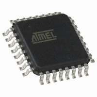
QT60248-ASG Atmel, QT60248-ASG Datasheet - Page 18

QT60248-ASG
Manufacturer Part Number
QT60248-ASG
Description
IC SENSOR QMATRIX 24CHAN 32TQFP
Manufacturer
Atmel
Series
QMatrix™, QProx™r
Type
Capacitiver
Datasheet
1.QT60168-ASG.pdf
(28 pages)
Specifications of QT60248-ASG
Number Of Inputs/keys
24 Key
Resolution (bits)
9, 11 b
Data Interface
Serial, SPI™
Voltage - Supply
3 V ~ 5 V
Current - Supply
25mA
Operating Temperature
-40°C ~ 105°C
Mounting Type
Surface Mount
Package / Case
32-TQFP, 32-VQFP
Output Type
Logic
Interface
SPI
Input Type
Logic
Operating Supply Voltage
3 V to 5 V
Maximum Operating Temperature
+ 105 C
Minimum Operating Temperature
- 40 C
Mounting Style
SMD/SMT
For Use With
427-1087 - BOARD EVAL QT60248-AS QMATRIX
Lead Free Status / RoHS Status
Lead free / RoHS Compliant
Other names
427-1108
Available stocks
Company
Part Number
Manufacturer
Quantity
Price
Company:
Part Number:
QT60248-ASG
Manufacturer:
ATMEL
Quantity:
101
Part Number:
QT60248-ASG
Manufacturer:
QUANTUM
Quantity:
20 000
5 Setups
The devices calibrate and process all signals using a
number of algorithms specifically designed to provide for
high survivability in the face of adverse environmental
challenges. They provide a large number of processing
options which can be user-selected to implement very
flexible, robust keypanel solutions.
User-defined Setups are employed to alter these algorithms
to suit each application. These setups are loaded into the
device in a block load over the serial interface. The Setups
are stored in an onboard eeprom array. After a setups block
load, the device should be reset to allow the new Setups
parameters to take effect. This reset can be either a
hardware or software reset.
Refer to Table 5.1, page 22 for a table of all Setups.
Block length issues: The setups block is 100 bytes long to
accommodate 24 keys. This can be a burden on smaller host
controllers with limited memory. In larger quantities the
devices can be procured with the setups block
preprogrammed from Quantum. If the application only
requires a small number of keys (such as 16) then the
setups table can be compressed in the host by filling large
stretches of the Setups area with nulls.
Many setups employ lookup-table value translation. The
Setups Block Summary on page 23 shows all translation
values.
Default Values shown are factory defaults.
5.1 Negative Threshold - NTHR
The negative threshold value is established relative to a
key’s signal reference value. The threshold is used to
determine key touch when crossed by a negative-going
signal swing after having been filtered by the detection
integrator. Larger absolute values of threshold desensitize
keys since the signal must travel farther in order to cross the
threshold level. Conversely, lower thresholds make keys
more sensitive.
As Cx and Cs drift, the reference point drift-compensates for
these changes at a user-settable rate; the threshold level is
recomputed whenever the reference point moves, and thus it
also is drift compensated.
The amount of NTHR required depends on the amount of
signal swing that occurs when a key is touched. Thicker
panels or smaller key geometries reduce ‘key gain’, ie signal
swing from touch, thus requiring smaller NTHR values to
detect touch.
The negative threshold is programmed on a
per-key basis using the Setup process. See table,
page 23.
Negative hysteresis: NHYST is fixed at 12.5% of
the negative threshold value and cannot be
altered .
Typical values:
Default value:
lQ
(7 to 12 counts of threshold; 4 is internally
added to NTHR to generate the threshold).
(10 counts of threshold)
3 to 8
6
Threshold
Hysteresis
Output
Figure 5-1 Thresholds and Drift Compensation
18
5.2 Positive Threshold - PTHR
The positive threshold is used to provide a mechanism for
recalibration of the reference point when a key's signal
moves abruptly to the positive. This condition is not normal,
and usually occurs only after a recalibration when an object
is touching the key and is subsequently removed. The desire
is normally to recover from these events quickly.
Positive hysteresis: PHYST is fixed at 12.5% of the positive
threshold value and cannot be altered.
Positive threshold levels are all fixed at 6 counts of signal
and cannot be modified.
5.3 Drift Compensation - NDRIFT, PDRIFT
Signals can drift because of changes in Cx and Cs over time
and temperature. It is crucial that such drift be compensated,
else false detections and sensitivity shifts can occur.
Drift compensation (Figure 5-1) is performed by making the
reference level track the raw signal at a slow rate, but only
while there is no detection in effect. The rate of adjustment
must be performed slowly, otherwise legitimate detections
could be ignored. The devices drift compensate using a
slew-rate limited change to the reference level; the threshold
and hysteresis values are slaved to this reference.
When a finger is sensed, the signal falls since the human
body acts to absorb charge from the cross-coupling between
X and Y lines. An isolated, untouched foreign object (a coin,
or a water film) will cause the signal to rise very slightly due
to an enhancement of coupling. This is contrary to the way
most capacitive sensors operate.
Once a finger is sensed, the drift compensation mechanism
ceases since the signal is legitimately detecting an object.
Drift compensation only works when the signal in question
has not crossed the negative threshold level.
The drift compensation mechanism can be asymmetric; the
drift-compensation can be made to occur in one direction
faster than it does in the other simply by changing the
NDRIFT Setup parameter. This can be done on a per-key
basis.
The PDRIFT parameter is fixed at 0.4 seconds per count of
reference drift.
Specifically, drift compensation should be set to compensate
faster for increasing signals than for decreasing signals.
Decreasing signals should not be compensated quickly,
since an approaching finger could be compensated for
partially or entirely before even touching the touch pad.
Signal
Reference
QT60248-AS R4.02/0405


