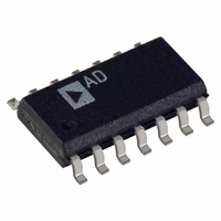
AD8174ARZ Analog Devices Inc, AD8174ARZ Datasheet - Page 12

AD8174ARZ
Manufacturer Part Number
AD8174ARZ
Description
IC MUX SWITCHNG W/AMP 4:1 14SOIC
Manufacturer
Analog Devices Inc
Datasheet
1.AD8170ARZ.pdf
(16 pages)
Specifications of AD8174ARZ
Applications
Multiplexer with Amplifier
Voltage - Supply
±4 V ~ 6 V
Package / Case
14-SOIC (3.9mm Width), 14-SOL
Mounting Type
Surface Mount
No. Of Circuits
4
Supply Current
9.7mA
Supply Voltage Range
± 4V To ± 6V
Operating Temperature Range
-40°C To +85°C
Analog Switch Case Style
SOIC
No. Of Pins
14
Lead Free Status / RoHS Status
Lead free / RoHS Compliant
Interface
-
Lead Free Status / RoHS Status
Lead free / RoHS Compliant, Lead free / RoHS Compliant
Available stocks
Company
Part Number
Manufacturer
Quantity
Price
Part Number:
AD8174ARZ
Manufacturer:
ADI/亚德诺
Quantity:
20 000
AD8170/AD8174
EVALUATION BOARD
Evaluation boards for the AD8170 and AD8174 are available
that have been carefully laid out and tested to demonstrate the
specified high speed performance of the devices. Figure 28 and
Figure 32 show the schematics of the AD8170 and AD8174
evaluation boards respectively. For ordering information, please
refer to the Ordering Guide.
Figure 29 shows the silkscreen of the component side of the
solder side of the AD8170 evaluation board. Figures 30 and 31
show the layout of the component side and solder side respec-
tively. The silkscreens and layout of the AD8174 evaluation
board are shown in Figures 33, 34, 35 and 36.
Figure 30. AD8170 Board Layout (Component Side)
SELECT
IN0
IN1
–V
S
R2
75
R1
50
R3
75
Figure 29. AD8170 Component Side Silkscreen
0.1µF
+
10µF
C2
C1
Figure 28. AD8170 Evaluation Board
GND
1
2
3
4
–VS
+1
–12–
AD8170
Both evaluation boards ship with 75
their analog inputs and analog outputs. To use the evaluation
board in nonvideo applications where 50
popular, these resistors can be replaced with 50
digital control pins are terminated with 50
easy connection to laboratory equipment.
The gain of the output current feedback op amp on both boards
has been set to +2. For other gains the two gain resistors can be
easily replaced. Refer to Table III for appropriate values at gains
other than +2.
For connection to external instruments, side-launched SMA
type connectors are provided. Space is also provided on the
board for the installation of SMB of SMC type connectors.
+1
+V
S
8
7
6
5
Figure 31. AD8170 Board Layout (Solder Side)
0.1µF
C4
+
10µF
C3
+V
S
R5
549
R4
549
75
R6
V
OUT
termination resistors on
termination is more
resistors to allow
values. The
REV. 0


