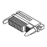
4-1926733-6 TE Connectivity, 4-1926733-6 Datasheet - Page 5

4-1926733-6
Manufacturer Part Number
4-1926733-6
Description
High Speed / Modular Connectors 25S 16P R/A RECPT SOCKET/RECPT CONTACT
Manufacturer
TE Connectivity
Specifications of 4-1926733-6
Pcb Mount Alignment
Without
Pcb Mount Retention
With
Pcb Mounting Orientation
Right Angle
Make First / Break Last
Yes
Product Line
MINIPAK HDL
Ul File Number
E28476
Termination Method To Pc Board
Through Hole - Press Fit
Sealed
No
Number Of Power Positions
16
Operating Voltage Reference
AC
Operating Voltage (vac)
250
Hot Pluggable
No
Tail Length (mm [in])
3.3 [0.13]
Tail Orientation
In-line
Profile Height (y-axis) (mm [in])
8.00 [0.315]
Number Of Signal Positions
25
Number Of Positions
41
Pcb Mount Retention Type
Screw Mount
Selectively Loaded
Yes
Centerline (mm [in])
2.00 [0.079]
Centerline, Power Contacts (mm [in])
2.75 [0.108]
Underplate Material Thickness (µm [?in])
1.27 [50.000]
Length (x-axis) (mm [in])
68.21 [2.690]
Width (z-axis) (mm [in])
36.58 [1.440]
Number Of Rows
1
Mating Retention
Without
Tail Plating Material
Bright Tin-Lead
Contact Type
Socket
Contact Base Material
Copper
Contact Plating, Mating Area, Material
Gold or Palladium Nickel or Performance Based
Contact Plating, Mating Area, Thickness (µm [?in])
0.762 [30]
Tail Plating, Thickness (µm [?in])
0.5 [20]
Underplate Material
Nickel
Contact Design
Single Beam
Connector Style
Receptacle
Mating Alignment
With
Housing Material
Crystal Polymer
Ul Flammability Rating
UL 94V-0
Housing Color
Black
Mating Alignment Type
Passive Guide
Connector Contact Configuration (no. Of Pos./type)
25/Signal, 16/AC Power
Custom Configurable
No
Rohs/elv Compliance
RoHS compliant, ELV compliant
Lead Free Solder Processes
Not relevant for lead free process
Rohs/elv Compliance History
Always was RoHS compliant
Agency/standard
UL, CSA
Ul Rating
Recognized
Ul Voltage Rating (vac)
250
Csa Certified
Yes
Operating Temperature (°c [°f])
-40 – +125 [-40 – +257]
Pcb Thickness, Recommended (mm [in])
1.40 [0.055]
Applies To
Printed Circuit Board
Board-to-board Configuration
Co-Planar
Contact Transmits (typical Application)
Signal (Data)/ Power
Application Use
Board-to-Board
Pick And Place Cover
Without
Packaging Method
Tray
Lead Free Status / Rohs Status
Details
Static load, transverse.
Contact retention.
Minute disturbance.
Com ponent heat resistance to wave
soldering.
Therm al shock.
Hum idity/tem perature cycling.
Rev B
Test Description
F1 = 100 N
F2 = 75 N
F3 = 50 N
No displacem ent of connector on
PCB likely to im pair norm al
operation.
See Note.
Signal contacts:
2 N m inim um in the m ating
direction.
9.5 N m inim um for pins in the
unm ating direction.
5 N m inim um for receptacles in the
unm ating direction.
Power contacts:
0.1 m m m axim um axial
displacem ent.
See Note.
See Note.
See Note.
See Note.
See Note.
Figure 3 (continued)
ENVIRONMENTAL
Requirem ent
Apply specified force in m iddle of
the specim en approxim ately 6 and
11 m m above the PCB.
See Figure 5.
Tyco Electronics 109-30-1.
Signal contacts:
Apply axial force of 2 N to pin and
receptacle contacts in the m ating
direction at a m axim um rate of 2.54
m m per m inute.
Apply axial force of 9.5 N (pin) and
5 N (receptacle) to pin contacts in
the unm ating direction at a
m axim um rate of 2.54 m m per
m inute.
Power contacts:
Apply axial force of 10 N to pin
contacts in the unm ating direction at
a m axim um rate of 2.54 m m per
m inute and hold for 5 seconds.
Apply axial force of 5 N to pin
contacts in the m ating direction at a
m axim um rate of 2.54 m m per
m inute and hold for 5 seconds.
Apply axial force of 5 N to
receptacle contacts in both the
m ating (against the tip of the pin)
and unm ating (against the back of
the contact) directions at a
m axim um rate of 2.54 m m per
m inute and hold for 5 seconds.
Unm ate and m ate each connector
pair a distance of approxim ately 0.1
m m .
Tyco Electronics 109-202,
Condition B.
EIA-364-32.
Subject unm ated specim ens to 5
cycles between -40 and 125 C with
30 m inute dwells at tem perature
extrem es and less than 1 m inute
transition between tem peratures.
EIA-364-31, Method III.
Subject unm ated specim ens to 10
cycles (10 days) between 25 and
65 C at 80 to 100% RH.
Procedure
108-2325
5 of 9


