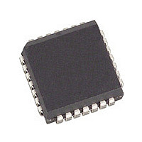
SL811HST Cypress Semiconductor Corp, SL811HST Datasheet - Page 11

SL811HST
Manufacturer Part Number
SL811HST
Description
Manufacturer
Cypress Semiconductor Corp
Datasheet
1.SL811HST.pdf
(32 pages)
Specifications of SL811HST
Operating Temperature (min)
0C
Operating Temperature Classification
Commercial
Package Type
PLCC
Rad Hardened
No
Lead Free Status / Rohs Status
Not Compliant
Available stocks
Company
Part Number
Manufacturer
Quantity
Price
Company:
Part Number:
SL811HST
Manufacturer:
CYP
Quantity:
3 000
Company:
Part Number:
SL811HST
Manufacturer:
CYPRESS
Quantity:
3 000
Company:
Part Number:
SL811HST
Manufacturer:
CYPRESS
Quantity:
5
Part Number:
SL811HST
Manufacturer:
CYPRESS/赛普拉斯
Quantity:
20 000
Company:
Part Number:
SL811HST-1.5
Manufacturer:
CYP
Quantity:
2 340
Part Number:
SL811HST-1.5
Manufacturer:
CYPRESS/赛普拉斯
Quantity:
20 000
Company:
Part Number:
SL811HST-AC
Manufacturer:
Cypress Semiconductor Corp
Quantity:
10 000
Company:
Part Number:
SL811HST-AXC
Manufacturer:
Cypress Semiconductor Corp
Quantity:
10 000
Part Number:
SL811HST-AXC
Manufacturer:
CYPRESS/赛普拉斯
Quantity:
20 000
Table 3-17. SOF High Counter when READ [Address 0Fh]
When WRITING to this register the bits definition are defined as follows.
Table 3-18. Control Register 2 when WRITTEN [Address 0Fh]
Note: Any Write to control register 0Fh will enable the
SL811HS full features bit. This is an internal bit of the SL811HS
which enables additional features not supported by the SL11H.
For SL11H hardware backward compatibility, this register
should not be accessed.
The USB-B register set can be used when SL811HS full
feature bit is enabled.
Example. To set up host to generate 1-ms SOF time:
The register 0Fh contains the upper 6 bits of the SOF timer.
Register 0Eh contains the lower 8 bits of the SOF timer. The
timer is based on an internal 12-MHz clock and uses a counter,
which counts down to zero from an initial value. To set the timer
for 1 ms time, the register 0Eh should be loaded with value
E0h and register 0Fh (Bits 0–5) should be loaded with 2Eh. To
Document 38-08008 Rev. *B
Bit Position
Master/Slave
SL811HS
selection
Bit 7
Bit 7
C13
5-0
7
6
Polarity Swap
D+/D– Data
Bit Name
SL811HS Master/Slave selection
SL811HS D+/D– Data Polarity Swap
SOF HIGH Counter Register
SL811HS
Bit 6
Bit 6
C12
Bit 5
Bit 5
C11
Bit 4
Bit 4
C10
Function
Master = 1, Slave = 0.
“1” = change polarity (low-speed)
“0” = no change of polarity (full-speed).
Write a value or read it back to SOF HIGH Counter Register.
SOF HIGH Counter Register
start the timer, bit 0 of register 05h (Control Register 1) should
be set to “1”, which enables hardware SOF generation. To load
both HIGH and LOW registers with the proper values the user
must follow this sequence:
1. Write E0h to register 0Eh. This sets the lower byte of the
2. Write AEh to register 0Fh, AEh will configure the part for
3. Enable bit 0 in register 05h. This enables hardware gener-
4. Set the ARM bit at address 00h. This starts the SOF gen-
SOF counter
Full-speed (no change of polarity) Host with bits 5–0 = 2Eh
for upper portion of SOF counter.
ation of SOF.
eration.
Bit 3
Bit 3
C9
Bit 2
Bit 2
C8
Bit 1
Bit 1
C7
SL811HS
Page 11 of 32
Bit 0
Bit 0
C6
[+] Feedback


