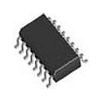
SI3018-F-GSR Silicon Laboratories Inc, SI3018-F-GSR Datasheet - Page 78

SI3018-F-GSR
Manufacturer Part Number
SI3018-F-GSR
Description
Manufacturer
Silicon Laboratories Inc
Datasheet
1.SI3018-F-GSR.pdf
(111 pages)
Specifications of SI3018-F-GSR
Lead Free Status / Rohs Status
Supplier Unconfirmed
- Current page: 78 of 111
- Download datasheet (2Mb)
Register 26. DC Termination Control
Reset settings = 0000_0000
Bit
7:6
5:4
3:2
1
0
Name
Type
Bit
Reserved
DCV[1:0]
MINI[1:0]
Name
DCR
ILIM
D7
TIP/RING Voltage Adjust.
These bits adjust the voltage on the DCT pin of the line-side device, which affects the TIP/
RING voltage on the line. Low-voltage countries should use a lower TIP/RING voltage. Rais-
ing the TIP/RING voltage can improve signal headroom.
Minimum Operational Loop Current.
Adjusts the minimum loop current at which the DAA can operate. Increasing the minimum
operational loop current can improve signal headroom at a lower TIP/RING voltage.
Current Limiting Enable.
0 = Current limiting mode disabled.
1 = Current limiting mode enabled. This mode limits loop current to a maximum of 60 mA per
the TBR21 standard.
DC Impedance Selection.
0 = 50 dc termination is selected. This mode should be used for all standard applications.
1 = 800 dc termination is selected.
These bits must always be written to 0.
DCV[1:0]
MINI[1:0]
DCV[1:0]
R/W
00
01
10
11
00
01
10
11
D6
DCT Pin Voltage
Min Loop Current
3.1 V
3.2 V
3.35 V
3.5 V
10 mA
12 mA
14 mA
16 mA
D5
MINI[1:0]
R/W
Rev. 1.31
D4
Function
D3
0
Si3050 + Si3018/19
D2
0
ILIM
R/W
D1
DCR
R/W
D0
79
Related parts for SI3018-F-GSR
Image
Part Number
Description
Manufacturer
Datasheet
Request
R
Part Number:
Description:
TSSOP 16/C°/SI3050 GLOBAL VOICE DAA LINE-SIDE - LEAD-FREE
Manufacturer:
Silicon Laboratories Inc
Part Number:
Description:
IC VOICE DAA GCI/PCM/SPI 16TSSOP
Manufacturer:
Silicon Laboratories Inc
Datasheet:

Part Number:
Description:
IC VOICE DAA GCI/PCM/SPI 16SOIC
Manufacturer:
Silicon Laboratories Inc
Datasheet:

Part Number:
Description:
IC VOICE DAA GCI/PCM/SPI 16SOIC
Manufacturer:
Silicon Laboratories Inc
Datasheet:

Part Number:
Description:
Modem Chip Chipset 16-Pin SOIC T/R
Manufacturer:
Silicon Laboratories Inc
Datasheet:
Part Number:
Description:
IC VOICE DAA GCI/PCM/SPI 16SOIC
Manufacturer:
Silicon Laboratories Inc

Part Number:
Description:
IC VOICE DAA GCI/PCM/SPI 16SOIC
Manufacturer:
Silicon Laboratories Inc
Datasheet:

Part Number:
Description:
IC VOICE DAA GCI/PCM/SPI 16SOIC
Manufacturer:
Silicon Laboratories Inc
Datasheet:

Part Number:
Description:
IC VOICE DAA GCI/PCM/SPI 16SOIC
Manufacturer:
Silicon Laboratories Inc
Datasheet:
Part Number:
Description:
IC VOICE DAA GCI/PCM/SPI 16TSSOP
Manufacturer:
Silicon Laboratories Inc
Datasheet:
Part Number:
Description:
IC VOICE DAA GCI/PCM/SPI 16TSSOP
Manufacturer:
Silicon Laboratories Inc
Part Number:
Description:
SMD/C°/SINGLE-ENDED OUTPUT SILICON OSCILLATOR
Manufacturer:
Silicon Laboratories Inc
Part Number:
Description:
Manufacturer:
Silicon Laboratories Inc
Datasheet:
Part Number:
Description:
N/A N/A/SI4010 AES KEYFOB DEMO WITH LCD RX
Manufacturer:
Silicon Laboratories Inc
Datasheet:


