LM4871LD/NOPB National Semiconductor, LM4871LD/NOPB Datasheet - Page 8
LM4871LD/NOPB
Manufacturer Part Number
LM4871LD/NOPB
Description
IC AMP AUDIO PWR 3W MONO AB 8LLP
Manufacturer
National Semiconductor
Series
Boomer®r
Type
Class ABr
Datasheet
1.LM4871MMNOPB.pdf
(16 pages)
Specifications of LM4871LD/NOPB
Output Type
1-Channel (Mono)
Max Output Power X Channels @ Load
3W x 1 @ 3 Ohm
Voltage - Supply
2 V ~ 5.5 V
Features
Shutdown, Thermal Protection
Mounting Type
Surface Mount
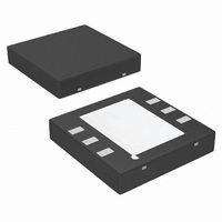
Package / Case
8-LLP
Amplifier Class
AB
No. Of Channels
1
Output Power
2.38W
Supply Voltage Range
2V To 5.5V
Load Impedance
3ohm
Operating Temperature Range
-40°C To +85°C
Amplifier Case Style
LLP
Rohs Compliant
Yes
Lead Free Status / RoHS Status
Lead free / RoHS Compliant
Other names
LM4871LD
LM4871LDTR
LM4871LDTR
Available stocks
Company
Part Number
Manufacturer
Quantity
Price

Company:
Part Number:
LM4871LD/NOPB
Manufacturer:
MICROCLOCK
Quantity:
400


www.national.com
Typical Performance Characteristics
Non-LD Specific Characteristics
Application Information
EXPOSED-DAP PACKAGE PCB MOUNTING
CONSIDERATION
The LM4871’s exposed-DAP (die attach paddle) package
(LD) provides a low thermal resistance between the die and
the PCB to which the part is mounted and soldered. This
allows rapid heat transfer from the die to the surrounding
PCB copper traces, ground plane, and surrounding air. The
result is a low voltage audio power amplifier that produces
2W at ≤ 1% THD with a 4Ω load. This high power is achieved
through careful consideration of necessary thermal design.
Failing to optimize thermal design may compromise the
LM4871’s high power performance and activate unwanted,
though necessary, thermal shutdown protection.
The LD package must have its DAP soldered to a copper
pad on the PCB. The DAP’s PCB copper pad is connected to
a large plane of continuous unbroken copper. This plane
forms a thermal mass, heat sink, and radiation area. Place
the heat sink area on either outside plane in the case of a
Frequency Response vs
Frequency Response
Input Capacitor Size
Open Loop
10000817
10000819
(Continued)
8
two-sided PCB, or on an inner layer of a board with more
than two layers. Connect the DAP copper pad to the inner
layer or backside copper heat sink area with 4(2x2) vias. The
via diameter should be 0.012in-0.013in with a 1.27mm pitch.
Ensure efficient thermal conductivity by plating through the
vias.
Best thermal performance is achieved with the largest prac-
tical heat sink area. If the heatsink and amplifier share the
same PCB layer, a nominal 2.5in
operation with a 4Ω load. Heatsink areas not placed on the
same PCB layer as the LM4871 should be 5in
same supply voltage and load resistance. The last two area
recommendations apply for 25˚C ambient temperature. In-
crease the area to compensate for ambient temperatures
above 25˚C. The LM4871’s power de-rating curve in the
Typical Performance Characteristics shows the maximum
power dissipation versus temperature. An example PCB lay-
out for the LD package is shown in the Demonstration
Board Layout section. Further detailed and specific infor-
mation concerning PCB layout, fabrication, and mounting an
Supply Current vs
Rejection Ratio
Supply Voltage
Power Supply
2
area is necessary for 5V
2
10000820
(min) for the
10000818
Related parts for LM4871LD/NOPB
Image
Part Number
Description
Manufacturer
Datasheet
Request
R

Part Number:
Description:
74C4600
Manufacturer:
National Semiconductor
Datasheet:

Part Number:
Description:
National Semiconductor [8-Bit D/A Converter]
Manufacturer:
National Semiconductor
Datasheet:
Part Number:
Description:
National Semiconductor [Media Coprocessor]
Manufacturer:
National Semiconductor
Datasheet:
Part Number:
Description:
Digitally Controlled Tone and Volume Circuit with Stereo Audio Power Amplifier, Microphone Preamp Stage and National 3D Sound
Manufacturer:
National Semiconductor
Datasheet:
Part Number:
Description:
Digitally Controlled Tone and Volume Circuit with Stereo Audio Power Amplifier, Microphone Preamp Stage and National 3D Sound
Manufacturer:
National Semiconductor
Datasheet:
Part Number:
Description:
AC97 Rev 2 Codec with Sample Rate Conversion and National 3D Sound
Manufacturer:
National Semiconductor
Part Number:
Description:
Manufacturer:
National Semiconductor
Datasheet:
Part Number:
Description:
Manufacturer:
National Semiconductor
Datasheet:
Part Number:
Description:
General Purpose, Low Voltage, Low Power, Rail-to-Rail Output Operational Amplifiers
Manufacturer:
National Semiconductor
Datasheet:
Part Number:
Description:
8-bit 20 MSPS flash A/D converter.
Manufacturer:
National Semiconductor
Datasheet:
Part Number:
Description:
Low Noise Quad Operational Amplifier
Manufacturer:
National Semiconductor
Datasheet:
Part Number:
Description:
Quad Differential Line Receivers
Manufacturer:
National Semiconductor
Datasheet:
Part Number:
Description:
Quad High Speed Trapezoidal? Bus Transceiver
Manufacturer:
National Semiconductor
Datasheet:
Part Number:
Description:
Dual Line Receiver
Manufacturer:
National Semiconductor
Datasheet: