LM4985TM/NOPB National Semiconductor, LM4985TM/NOPB Datasheet
LM4985TM/NOPB
Specifications of LM4985TM/NOPB


Related parts for LM4985TM/NOPB

LM4985TM/NOPB Summary of contents
Page 1
... LM4985 can also be configured for single-ended capaci- tively coupled outputs. The LM4985 features a current shutdown mode for mi- cropower dissipation and thermal shutdown protection. Boomer ® registered trademark of National Semiconductor Corporation. © 2006 National Semiconductor Corporation Key Specifications (V j PSRR: 217Hz and 1kHz Output Capacitor-less (OCL) ...
Page 2
Block Diagram www.national.com FIGURE 1. Block Diagram 2 201697E9 ...
Page 3
Typical Application FIGURE 2. Typical Capacitively Coupled Output Configuration Circuit FIGURE 3. Typical OCL Output Configuration Circuit 3 201697F0 201697F1 www.national.com ...
Page 4
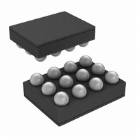
Connection Diagrams micro SMD Package Top View Order Number LM4985TM See NS Package Number TMD12AAA Reference www.national.com 20169715 Pin Reference, Name, and Function Name ADR IN2 OUT2 SDA ...
Page 5
... Absolute Maximum Ratings If Military/Aerospace specified devices are required, please contact the National Semiconductor Sales Office/ Distributors for availability and specifications. 2 Supply Voltage ( Storage Temperature Input Voltage (IN1, IN2, OUT1, OUT2, BYPASS, CNTGND, GND pins relative to the V pin) DD Input Voltage (ADR, SDA, SCL ...
Page 6
Electrical Characteristics V The following specifications apply for R 25˚C. Symbol Parameter T Wake Up Time form Shutdown WU R Input Resistance IN A Minimum Gain VMIN A Maximum Gain VMAX ∆A Gain Accuracy per Step V V Output Offset ...
Page 7
Electrical Characteristics V The following specifications apply for R 25˚C. Symbol Parameter THD+N Total Harmonic Distortion + Noise V Output Noise Voltage ON PSRR Power Supply Rejection Ratio Xtalk Channel-to-Channel Crosstalk T Wake Up Time from Shutdown WU R Input ...
Page 8
Electrical Characteristics V The following specifications apply for R 25˚C. Symbol Parameter I Quiescent Power Supply Current DD I Shutdown Current SD V Logic Voltage Input High SDIH V Logic Voltage Input Low SDIL P Output Power O THD+N Total ...
Page 9
Electrical Characteristics V The following specifications apply for R 25˚C. Symbol Parameter A Maximum Gain VMAX ∆A Gain Accuracy per Step V V Output Offset Voltage OS Note 1: All voltages are measured with respect to the GND pin unless ...
Page 10
Typical Performance Characteristics T = 25˚ 0dB 1kHz unless otherwise stated THD+N vs Frequency V = 2.5V 20mW, C-CUPL OUT THD+N vs Frequency ...
Page 11
Typical Performance Characteristics THD+N vs Frequency V = 2.5V 16Ω 20mW, OCL OUT THD+N vs Frequency V = 5.0V 16Ω 50mW, OCL OUT THD+N vs Frequency V = ...
Page 12
Typical Performance Characteristics THD+N vs Output Power V = 2.5V C-CUPL THD+N vs Output Power V = 5.0V C-CUPL THD+N vs Output Power V = 3.6V C-CUPL www.national.com (Continued) = 16Ω ...
Page 13
Typical Performance Characteristics THD+N vs Output Power V = 2.5V 16Ω OCL THD+N vs Output Power V = 5.0V 16Ω OCL THD+N vs Output Power V = 3.6V 32Ω DD ...
Page 14
Typical Performance Characteristics PSRR vs Frequency V = 2.5V 200mVpp, OCL RIPPLE PSRR vs Frequency V = 5.0V 200mVpp, OCL RIPPLE PSRR vs Frequency V = 3.6V ...
Page 15
Typical Performance Characteristics PSRR vs Frequency V = 2.5V 16Ω 200mVpp, C-CUPL RIPPLE PSRR vs Frequency V = 5.0V 16Ω 200mVpp, C-CUPL RIPPLE PSRR vs Frequency V = ...
Page 16
Typical Performance Characteristics Crosstalk vs Frequency V = 2.5V 20mW. OCL OUT Crosstalk vs Frequency V = 5.0V 40mW, OCL OUT Crosstalk vs Frequency V = 3.6V ...
Page 17
Typical Performance Characteristics Crosstalk vs Frequency V = 2.5V 16Ω 20mW, C-CUPL OUT Crosstalk vs Frequency V = 5.0V 16Ω 50mW, C-CUPL OUT Crosstalk vs Frequency V = ...
Page 18
Typical Performance Characteristics Load Dissipation vs Amplifier Dissipation V = 2.5V, C-CUPL DD Load Dissipation vs Amplifier Dissipation V = 5.0V, C-CUPL DD Load Dissipation vs Amplifier Dissipation V = 3.6V, OCL DD www.national.com (Continued) Load Dissipation vs Amplifier Dissipation ...
Page 19
Typical Performance Characteristics Output Power vs Load Resistance V = 2.5V, C-CUPL DD Output Power vs Load Resistance V = 5.0V, C-CUPL DD Output Power vs Load Resistance V = 3.6V, OCL DD (Continued) Output Power vs Load Resistance V ...
Page 20
Typical Performance Characteristics Output Power vs Supply Voltage R = 16Ω, C-CUPL L Output Power vs Supply Voltage R = 16Ω, OCL L Supply Current vs Supply Voltage R = 16Ω, C-CUPL L www.national.com (Continued) Output Power vs Supply Voltage ...
Page 21
Typical Performance Characteristics Supply Current vs Supply Voltage R = 16Ω, OCL L Gain vs Volume Steps V = 2.5V 16Ω, OCL CC L Gain vs Volume Steps 16Ω, OCL CC L (Continued) ...
Page 22
Typical Performance Characteristics Gain vs Volume Steps V = 3.6V 16Ω, C-CUPL CC L Gain vs Volume Steps V = 2.5V 32Ω, OCL CC L Gain vs Volume Steps 32Ω, OCL ...
Page 23
Typical Performance Characteristics Gain vs Volume Steps V = 3.6V 32Ω, C-CUPL CC L (Continued) Gain vs Volume Steps V CC 201697G1 32Ω, C-CUPL L 201697G5 www.national.com ...
Page 24
Application Information AMPLIFIER CONFIGURATION EXPLANATION As shown in Figure 1, the LM4985 has three internal power amplifiers. Two of the amplifiers which amplify signals ap- plied to their inputs, have internally configurable gain. The remaining third amplifier provides both half-supply ...
Page 25
Application Information coupling capacitor requires more charge to reach its quies- cent DC voltage. This charge comes from the output via the feedback Thus, by minimizing the capacitor size based on necessary low frequency response, turn-on time can be minimized. ...
Page 26
I C Control Register Table 1 shows the actions that are implemented by manipulating the bits within the two internal I Table 1. LM4985 I LM4985 I2C Contorl Register Addressing and Data Chart A6 A5 I2C Address 1 1 ...
Page 27
Volume Control Settings Binary Values The minimum volume setting is set to –76dB when 00000 is loaded into the volume control register. Incrementing the volume control register in binary fashion increases the volume control setting, reaching full scale at 11111. ...
Page 28
Revision History Rev 1.0 www.national.com Date 05/17/06 Initial WEB release. 28 Description ...
Page 29
... BANNED SUBSTANCE COMPLIANCE National Semiconductor follows the provisions of the Product Stewardship Guide for Customers (CSP-9-111C2) and Banned Substances and Materials of Interest Specification (CSP-9-111S2) for regulatory environmental compliance. Details may be found at: www.national.com/quality/green. ...