LM3876T/NOPB National Semiconductor, LM3876T/NOPB Datasheet - Page 4
LM3876T/NOPB
Manufacturer Part Number
LM3876T/NOPB
Description
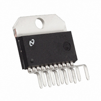
IC AMP AUDIO PWR 56W AB TO220-11
Manufacturer
National Semiconductor
Series
Overture™r
Type
Class ABr
Specifications of LM3876T/NOPB
Output Type
1-Channel (Mono)
Max Output Power X Channels @ Load
56W x 1 @ 8 Ohm
Voltage - Supply
20 V ~ 84 V, ±10 V ~ 42 V
Features
Mute, Short-Circuit and Thermal Protection
Mounting Type
Through Hole
Package / Case
TO-220-11 (Bent and Staggered Leads)
Amplifier Type
Audio
Bandwidth
8 MHz
Common Mode Rejection Ratio
120
Current, Input Bias
0.2 μA
Current, Input Offset
0.01 μA
Current, Output
6 A
Current, Supply
30 mA
Harmonic Distortion
0.06 %
Impedance, Thermal
43 °C/W
Open Loop Gain
120
Package Type
TO220-11
Power Dissipation
125 W
Slew Rate
11
Temperature, Operating, Range
-20 to +85 °C
Voltage, Input
≤80 V
Voltage, Input Offset
1 mV
Voltage, Noise
2 μV
Voltage, Supply
24 to 84 V
Amplifier Class
AB
No. Of Channels
1
Output Power
56W
Supply Voltage Range
24V To 84V
Load Impedance
8ohm
Operating Temperature Range
-20°C To +85°C
Amplifier Case Style
TO-220
Rohs Compliant
Yes
Lead Free Status / RoHS Status
Lead free / RoHS Compliant
Other names
*LM3876T
*LM3876T/NOPB
LM3876T
*LM3876T/NOPB
LM3876T


www.national.com
GBWP
e
SNR
IMD
IN
Electrical Characteristics
Symbol
Note 2: DC Electrical Test; refer to Test Circuit #1.
Note 3: AC Electrical Test; refer to Test Circuit #2.
Note 4: All voltages are measured with respect to the GND pin (pin 7), unless otherwise specified.
Note 5: Absolute Maximum Ratings indicate limits beyond which damage to the device may occur. Operating Ratings indicate conditions for which the device is
functional, but do not guarantee specific performance limits. Electrical Characteristics state DC and AC electrical specifications under particular test conditions which
guarantee specific performance limits. This assumes that the device is within the Operating Ratings. Specifications are not guaranteed for parameters where no limit
is given, however, the typical value is a good indication of device performance.
Note 6: For operating at case temperatures above 25˚C, the device must be derated based on a 150˚C maximum junction temperature and a thermal resistance
of θ
Note 7: Human body model, 100 pF discharged through a 1.5 kΩ resistor.
Note 8: The operating junction temperature maximum is 150˚C, however, the instantaneous Safe Operating Area temperature is 250˚C.
Note 9: Typicals are measured at 25˚C and represent the parametric norm.
Note 10: Limits are guaranteed to National’s AOQL (Average Outgoing Quality Level).
Note 11: The LM3876T package TA11B is a non-isolated package, setting the tab of the device and the heat sink at V
mounted to the heat sink using only thermal compound. If a mica washer is used in addition to thermal compound, θ
will be isolated from V
Note 12: The feedback compensation network limits the bandwidth of the closed-loop response and so the slew rate will be reduced due to the high frequency
roll-off. Without feedback compensation, the slew rate is typically 16V/µs.
Note 13: V
Note 14: The output dropout voltage is the supply voltage minus the clipping voltage. Refer to the Clipping Voltage vs Supply Voltage graph in the Typical
Performance Characteristics section.
The following specifications apply for V
apply for T
(Note 3) Input Noise
JC
= 1.0 ˚C/W (junction to case). Refer to the Thermal Resistance figure in the Application Information section under Thermal Considerations.
−
must have at least −9V at its pin with reference to ground in order for the under-voltage protection circuitry to be disabled.
Gain-Bandwidth Product
Signal-to-Noise Ratio
Intermodulation Distortion Test
A
= 25˚C.
−
.
Parameter
+
= +35V, V
(Notes 4, 5) (Continued)
−
|V
f
IHF — A Weighting Filter
R
P
Measured at 1 kHz, R
P
Measured at 1 kHz, R
Ppk= 100W, A-Weighted,
Measured at 1 kHz, R
60 Hz, 7 kHz, 4:1 (SMPTE)
60 Hz, 7 kHz, 1:1 (SMPTE)
O
O
O
= −35V, I
IN
+
= 100 kHz, V
| = |V
= 1W, A-Weighted,
= 40W, A-Weighted,
= 600Ω (Input Referred)
−
| = 40V
4
MUTE
Conditions
IN
= −0.5 mA with R
= 50 mVrms
S
S
S
= 25Ω
= 25Ω
= 25Ω
L
= 8Ω unless otherwise specified. Limits
CS
(case to sink) is increased, but the heat sink
−
potential when the LM3876 is directly
(Note 9) (Note 10)
Typical
0.004
0.006
114
122
2.0
98
8
LM3876
Limit
2
8
MHz (min)
µV (max)
(Limits)
Units
dB
dB
dB
%
Related parts for LM3876T/NOPB
Image
Part Number
Description
Manufacturer
Datasheet
Request
R

Part Number:
Description:
92F296
Manufacturer:
National Semiconductor
Datasheet:

Part Number:
Description:
LM387/LM387A Low Noise Dual Preamplifier
Manufacturer:
National Semiconductor
Datasheet:
Part Number:
Description:
LM387 - Low Noise Dual Preamplifier [Discontinued]
Manufacturer:
National Semiconductor
Part Number:
Description:
National Semiconductor [8-Bit D/A Converter]
Manufacturer:
National Semiconductor
Datasheet:
Part Number:
Description:
National Semiconductor [Media Coprocessor]
Manufacturer:
National Semiconductor
Datasheet:
Part Number:
Description:
Digitally Controlled Tone and Volume Circuit with Stereo Audio Power Amplifier, Microphone Preamp Stage and National 3D Sound
Manufacturer:
National Semiconductor
Datasheet:
Part Number:
Description:
Digitally Controlled Tone and Volume Circuit with Stereo Audio Power Amplifier, Microphone Preamp Stage and National 3D Sound
Manufacturer:
National Semiconductor
Datasheet:
Part Number:
Description:
AC97 Rev 2 Codec with Sample Rate Conversion and National 3D Sound
Manufacturer:
National Semiconductor
Part Number:
Description:
Manufacturer:
National Semiconductor
Datasheet:
Part Number:
Description:
Manufacturer:
National Semiconductor
Datasheet:
Part Number:
Description:
General Purpose, Low Voltage, Low Power, Rail-to-Rail Output Operational Amplifiers
Manufacturer:
National Semiconductor
Datasheet:
Part Number:
Description:
8-bit 20 MSPS flash A/D converter.
Manufacturer:
National Semiconductor
Datasheet:
Part Number:
Description:
Low Noise Quad Operational Amplifier
Manufacturer:
National Semiconductor
Datasheet:
Part Number:
Description:
Quad Differential Line Receivers
Manufacturer:
National Semiconductor
Datasheet: