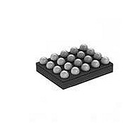
MAX97002EWP+T Maxim Integrated Products, MAX97002EWP+T Datasheet - Page 21

MAX97002EWP+T
Manufacturer Part Number
MAX97002EWP+T
Description
IC AUDIO SUBSYSTEM 20WLP
Manufacturer
Maxim Integrated Products
Series
DirectDrive™r
Type
Class Dr
Datasheet
1.MAX97002EWPT.pdf
(37 pages)
Specifications of MAX97002EWP+T
Output Type
1-Channel (Mono) with Stereo Headphones
Max Output Power X Channels @ Load
920mW x 1 @ 8 Ohm; 37mW x 2 @ 16 Ohm
Voltage - Supply
2.7 V ~ 5.5 V
Features
Depop, Differential Inputs, I²C, Mute, Shutdown, Volume Control
Mounting Type
Surface Mount
Package / Case
20-WLP
Product
Class-D
Output Power
700 mW
Available Set Gain
12 dB
Common Mode Rejection Ratio (min)
32 dB to 55 dB
Thd Plus Noise
0.05 %
Operating Supply Voltage
2.7 V to 5.5 V
Supply Current
0.32 mA to 1.85 mA
Maximum Power Dissipation
1040 mW
Maximum Operating Temperature
+ 80 C
Mounting Style
SMD/SMT
Audio Load Resistance
41.2 KOhms
Input Signal Type
Differential or Single
Minimum Operating Temperature
- 40 C
Output Signal Type
Differential
Supply Voltage (max)
5.5 V
Supply Voltage (min)
2.7 V
Lead Free Status / RoHS Status
Lead free / RoHS Compliant
Other names
MAX97002EWP+T
The MAX97002 speaker amplifiers integrate a limiter
to provide speaker protection and audio compression.
When enabled, the limiter monitors the audio signal at
the output of the Class D speaker amplifier and decreas-
es the gain if the distortion exceeds the predefined
threshold. The limiter automatically tracks the battery
voltage to reduce the gain as the battery voltage drops.
Figure 5 shows the typical output vs. input curves with
and without the distortion limiter. The dotted line shows
the maximum gain for a given distortion limit without
the distortion limiter. The solid line shows how, with the
distortion limiter enabled, the gain can be increased
without exceeding the set distortion limit. When the
limiter is enabled, selecting a high gain level results in
peak signals being attenuated while low signals are left
unchanged. This increases the perceived loudness with-
out the harshness of a clipped waveform.
The MAX97002 integrates a DPST analog audio switch
that connects COM1 and COM2 to OUTP and OUTN,
respectively. Unlike discrete solutions, the switch design
reduces coupling of Class D switching noise to the COM_
inputs. This eliminates the need for a costly T-switch.
Drive COM1 and COM2 with a low-impedance source
to minimize noise on the pins. In applications that do not
require the analog switch, leave COM1 and COM2 uncon-
nected. When applying signal on COM1 and COM2, dis-
able the Class D amplifier before closing the switch.
Traditional single-supply headphone amplifiers have
outputs biased at a nominal DC voltage (typically half
the supply). Large coupling capacitors are needed to
block this DC bias from the headphone. Without these
capacitors, a significant amount of DC current flows to
the headphone, resulting in unnecessary power dis-
sipation and possible damage to both headphone and
headphone amplifier.
Maxim’s DirectDrive
to create an internal negative supply voltage. This allows
the headphone outputs of the MAX97002 to be biased
at GND while operating from a single supply (Figure 6).
Without a DC component, there is no need for the large
DC-blocking capacitors. Instead of two large (220FF,
typ) capacitors, the MAX97002 charge pump requires
two small ceramic capacitors, conserving board space,
reducing cost, and improving the frequency response
of the headphone amplifier. See the Output Power
Speaker and Class H Headphone Amplifiers
®
architecture uses a charge pump
Audio Subsystem with Mono Class D
Headphone Amplifier
Distortion Limiter
Analog Switch
DirectDrive
Figure 5. Limiter Gain Curve
Figure 6.Traditional Amplifier Output vs. MAX97002
DirectDrive Output
DirectDrive is a registered trademark of Maxim Integrated
Products, Inc.
vs. Load Resistance graph in the Typical Operating
Characteristics for details of the possible capacitor
sizes. There is a low DC voltage on the amplifier out-
puts due to amplifier offset. However, the offset of the
MAX97002 is typically Q0.6mV, which, when combined
with a 32I load, results in less than 50FA of DC current
flow to the headphones.
CONVENTIONAL AMPLIFIER BIASING SCHEME
MAXIMUM THD+N
DirectDrive AMPLIFIER BIASING SCHEME
LEVEL
V
OUT
V
V
GND
+V
SGND
-V
V
IN
DD
DD
DD
DD
/ 2
21


