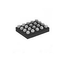
MAX97002EWP+T Maxim Integrated Products, MAX97002EWP+T Datasheet - Page 35

MAX97002EWP+T
Manufacturer Part Number
MAX97002EWP+T
Description
IC AUDIO SUBSYSTEM 20WLP
Manufacturer
Maxim Integrated Products
Series
DirectDrive™r
Type
Class Dr
Datasheet
1.MAX97002EWPT.pdf
(37 pages)
Specifications of MAX97002EWP+T
Output Type
1-Channel (Mono) with Stereo Headphones
Max Output Power X Channels @ Load
920mW x 1 @ 8 Ohm; 37mW x 2 @ 16 Ohm
Voltage - Supply
2.7 V ~ 5.5 V
Features
Depop, Differential Inputs, I²C, Mute, Shutdown, Volume Control
Mounting Type
Surface Mount
Package / Case
20-WLP
Product
Class-D
Output Power
700 mW
Available Set Gain
12 dB
Common Mode Rejection Ratio (min)
32 dB to 55 dB
Thd Plus Noise
0.05 %
Operating Supply Voltage
2.7 V to 5.5 V
Supply Current
0.32 mA to 1.85 mA
Maximum Power Dissipation
1040 mW
Maximum Operating Temperature
+ 80 C
Mounting Style
SMD/SMT
Audio Load Resistance
41.2 KOhms
Input Signal Type
Differential or Single
Minimum Operating Temperature
- 40 C
Output Signal Type
Differential
Supply Voltage (max)
5.5 V
Supply Voltage (min)
2.7 V
Lead Free Status / RoHS Status
Lead free / RoHS Compliant
Other names
MAX97002EWP+T
Bypass PVDD to GND with as little trace length as pos-
sible. Connect OUTP and OUTN to the speaker using
the shortest and widest traces possible. Reducing trace
length minimizes radiated EMI. Route OUTP/OUTN as
a differential pair on the PCB to minimize the loop area,
thereby reducing the inductance of the circuit. If filter
components are used on the speaker outputs, be sure
to locate them as close as possible to the MAX97002
to ensure maximum effectiveness. Minimize the trace
length from any ground tied passive components to
GND to further minimize radiated EMI.
An evaluation kit (EV kit) is available to provide an
example layout for the MAX97002. The EV kit allows
quick setup of the MAX97002 and includes easy-to-use
software, allowing all internal registers to be controlled.
For the latest application details on WLP construction,
dimensions, tape carrier information, PCB techniques,
bump-pad layout, and the recommended reflow temper-
ature profile, as well as the latest information on reliability
testing results, refer to the Application Note 1891: Wafer-
Level Packaging (WLP) and Its Applications on Maxim’s
website at www.maxim-ic.com/ucsp. See Figure 15 for
the recommended PCB footprint for the MAX97002.
Speaker and Class H Headphone Amplifiers
WLP Applications Information
Audio Subsystem with Mono Class D
Figure 15. Recommended PCB Footprint
0.25mm
0.22mm
35


