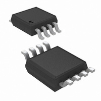
LM4875MM/NOPB National Semiconductor, LM4875MM/NOPB Datasheet - Page 7

LM4875MM/NOPB
Manufacturer Part Number
LM4875MM/NOPB
Description
IC AMP AUDIO PWR 1W MONO 8MSOP
Manufacturer
National Semiconductor
Series
Boomer®r
Type
Class ABr
Datasheet
1.LM4875MXNOPB.pdf
(13 pages)
Specifications of LM4875MM/NOPB
Output Type
1-Channel (Mono) with Mono Headphones
Max Output Power X Channels @ Load
1W x 1 @ 8 Ohm; 110mW x 1 @ 32 Ohm
Voltage - Supply
2.7 V ~ 5.5 V
Features
Depop, Mute, Shutdown, Thermal Protection, Volume Control
Mounting Type
Surface Mount
Package / Case
8-MSOP, Micro8™, 8-uMAX, 8-uSOP,
Lead Free Status / RoHS Status
Lead free / RoHS Compliant
Other names
LM4875MM
Typical Performance Characteristics
Application Information
BRIDGE CONFIGURATION EXPLANATION
As shown in Figure 1, the LM4875 consists of two opera-
tional amplifiers internally. An external DC voltage sets the
closed-loop gain of the first amplifier, whereas two internal
20kΩ resistors set the second amplifier’s gain at -1. The
LM4875 can be used to drive a speaker connected between
the two amplifier outputs or a monaural headphone con-
nected between V
Figure 1 shows that the output of Amp1 serves as the input
to Amp2. This results in both amplifiers producing signals
that are identical in magnitude, but 180˚ out of phase.
Taking advantage of this phase difference, a load placed
between V
referred to as “bridge mode“ ). This mode is different from
single-ended driven loads that are connected between a
single amplifier’s output and ground.
Bridge mode has a distinct advantage over the single-ended
configuration: its differential drive to the load doubles the
output swing for a specified supply voltage. This results in
four times the output power when compared to a single-
ended amplifier under the same conditions. This increase in
attainable output assumes that the amplifier is not current
limited or the output signal is not clipped. To ensure mini-
O
Supply Current vs Supply Voltage
1 and V
Output Power vs Supply Voltage
O
1 and GND.
O
2 is driven differentially (commonly
10104233
10104231
7
(Continued)
mum output signal clipping when choosing an amplifier’s
closed-loop gain, refer to the Audio Power Amplifier De-
sign section.
Another advantage of the differential bridge output is no net
DC voltage across load. This results from biasing V
V
that single supply, single-ended amplifiers require. Eliminat-
ing an output coupling capacitor in a single-ended configu-
ration forces a single supply amplifier’s half-supply bias volt-
age across the load. The current flow created by the half-
supply bias voltage increases internal IC power dissipation
and may permanently damage loads such as speakers.
POWER DISSIPATION
Power dissipation is a major concern when designing a
successful bridged or single-ended amplifier. Equation (1)
states the maximum power dissipation point for a single-
ended amplifier operating at a given supply voltage and
driving a specified output load.
However, a direct consequence of the increased power de-
livered to the load by a bridge amplifier is an increase in
internal power dissipation point for a bridge amplifier oper-
ating at the same given conditions.
The LM4875 has two operational amplifiers in one package
and the maximum internal power dissipation is 4 times that
O
2 at half-supply. This eliminates the coupling capacitor
P
P
DMAX
Output Power vs Supply Voltage
DMAX
= 4*(V
= (V
DD
DD
)
2
)
/(2π
2
/(2π
2
R
2
R
L
) Single-Ended
L
) Bridge Mode
10104232
www.national.com
O
1 and
(1)
(2)


