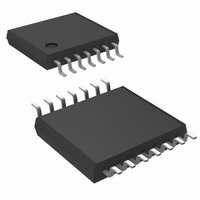
LM4854MTX/NOPB National Semiconductor, LM4854MTX/NOPB Datasheet - Page 24

LM4854MTX/NOPB
Manufacturer Part Number
LM4854MTX/NOPB
Description
IC AMP AUDIO PWR 2.3W AB 14TSSOP
Manufacturer
National Semiconductor
Series
Boomer®r
Type
Class ABr
Datasheet
1.LM4854MTXNOPB.pdf
(29 pages)
Specifications of LM4854MTX/NOPB
Output Type
1-Channel (Mono) with Stereo Headphones
Max Output Power X Channels @ Load
2.3W x 1 @ 3.2 Ohm; 200mW x 2 @ 16 Ohm
Voltage - Supply
2.4 V ~ 5.5 V
Features
Depop, Shutdown, Standby, Thermal Protection
Mounting Type
Surface Mount
Package / Case
14-TSSOP
Operational Class
Class-AB
Audio Amplifier Function
Headphone/Speaker
Total Harmonic Distortion
0.3@32Ohm@50mW%
Single Supply Voltage (typ)
3/5V
Dual Supply Voltage (typ)
Not RequiredV
Power Supply Requirement
Single
Rail/rail I/o Type
No
Power Supply Rejection Ratio
71dB
Single Supply Voltage (min)
2.4V
Single Supply Voltage (max)
5.5V
Dual Supply Voltage (min)
Not RequiredV
Dual Supply Voltage (max)
Not RequiredV
Operating Temp Range
-40C to 85C
Operating Temperature Classification
Industrial
Mounting
Surface Mount
Pin Count
14
Package Type
TSSOP
Lead Free Status / RoHS Status
Lead free / RoHS Compliant
Other names
LM4854MTX
www.national.com
Application Information
The product of the desired high frequency cutoff (100kHz in
this example) and the differential gain AVD, determines the
upper passband response limit. With AVD = 3 and fH =
100kHz, the closed-loop gain bandwidth product (GBWP) is
300kHz. This is less than the LM4854’s 3.5MHz GBWP. With
this margin, the amplifier can be used in designs that require
more differential gain while avoiding performance restricting
bandwidth limitations.
RECOMMENDED PRINTED CIRCUIT BOARD LAYOUT
Figures 5 through 9 show the recommended four-layer PC
board layout that is optimized for the micro SMD-packaged
LM4854 and associated external components. Figures 10
Demonstration Board Layout
FIGURE 5. Recommended microSMD PC Board
FIGURE 6. Recommended microSMD PC Board
Component-Side SilkScreen
Component-Side Layout
Layout:
Layout:
(Continued)
20038221
20038222
24
through 12 show the recommended two-layer PC board
layout that is optimized for the TSSOP-packaged LM4854
and associated external components. Figures 13 through 17
show the recommended four-layer PC board layout that is
optimized for the LLP-packaged LM4854 and associate ex-
ternal components.
These circuits are designed for use with an external 5V
supply and 8Ω(min) speakers.These circuit boards are easy
to use. Apply 5V and ground to the board’s V
pads, respectively. Connect a speaker between the board’s
L-OUT and BTL-OUT or headphones to the headphone jack
(L-OUT and R-OUT outputs).
FIGURE 7. Recommended microSMD PC Board
FIGURE 8. Recommended microSMD PC Board
Lower Inner-Layout Layer
Upper Inner-Layer Layout
Layout:
Layout:
DD
20038223
20038224
and GND


