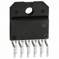
LM4700TF/NOPB National Semiconductor, LM4700TF/NOPB Datasheet

LM4700TF/NOPB
Specifications of LM4700TF/NOPB
*LM4700TF/NOPB
LM4700TF
Related parts for LM4700TF/NOPB
LM4700TF/NOPB Summary of contents
Page 1
... FIGURE 1. Typical Audio Amplifier Application Circuit SPiKe ™ Protection and Overture ™ are trademarks of National Semiconductor Corporation. © 2004 National Semiconductor Corporation Key Specifications n THD+N at 1kHz at continuous average output power of 25W into 8Ω: n THD+N from 20Hz to 20kHz at 30W of continuous average output power into 8Ω: ...
Page 2
Connection Diagram See NS Package Number TF11B for Staggered Lead Isolated Package See TA11B for Staggered Lead Non-Isolated Package www.national.com Isolated Plastic Package 01236902 Top View Order Number LM4700TF or LM4700T 2 ...
Page 3
... Absolute Maximum Ratings 5) If Military/Aerospace specified devices are required, please contact the National Semiconductor Sales Office/ Distributors for availability and specifications. Supply Voltage | (No Signal) Supply Voltage | (with Input and Load) Common Mode Input Voltage Differential Input Voltage Output Current Power Dissipation (Note 6) ...
Page 4
... Increased power dissipation will require a larger heat sink as explained in the Application Information section. Note 14: Preliminary engineering evaluation of θ data to this point. Please contact your local National Semiconductor sales representative for more information. www.national.com (Continued) = +28V − ...
Page 5
Test Circuit #1 (Note 2) (DC Electrical Test Circuit) Test Circuit #2 (Note 3) (AC Electrical Test Circuit) 01236904 5 01236903 www.national.com ...
Page 6
Bridged Amplifier Application Circuit Single Supply Application Circuit FIGURE 3. Single Supply Amplifier Application Circuit www.national.com FIGURE 2. Bridged Amplifier Application Circuit 6 01236905 01236906 ...
Page 7
Auxillary Amplifier Application Circuit FIGURE 4. Auxillary Amplifier Application Circuit 7 01236907 www.national.com ...
Page 8
Equivalent Schematic Protection Circuitry) www.national.com (Excluding Active 8 01236908 ...
Page 9
External Components Description Components 1 R Prevents currents from entering the amplifier’s non-inverting input which may be passed through to the B load upon power down of the system due to the low input impedance of the circuitry when the ...
Page 10
Typical Performance Characteristics THD + N vs Frequency THD + N vs Frequency THD + N vs Output Power www.national.com THD + N vs Frequency 01236910 THD + N vs Output Power 01236912 THD + N vs Output Power 01236914 ...
Page 11
Typical Performance Characteristics THD + N vs Output Power THD + N vs Output Power Clipping Voltage vs Supply Voltage (Continued) THD + N vs Output Power 01236916 01236918 01236920 11 01236917 Clipping Voltage vs Supply Voltage 01236919 Clipping Voltage ...
Page 12
Typical Performance Characteristics Power Dissipation vs Output Power Power Dissipation vs Output Power Output Power vs Supply Voltage www.national.com (Continued) 01236922 01236924 01236926 12 Power Dissipation vs Ouput Power 01236923 Output Power vs Load Resistance 01236925 Output Mute vs Mute ...
Page 13
Typical Performance Characteristics Pulse Response Output Mute vs Mute Pin Voltage Common-Mode Rejection Ratio (Continued) 01236928 01236930 01236932 13 Large Signal Response 01236929 Power Supply Rejection Ratio 01236931 Open Loop Frequency Response 01236933 www.national.com ...
Page 14
Typical Performance Characteristics Safe Area Supply Current vs Supply Voltage Pulse Thermal Resistance www.national.com (Continued) Spike Protection Response 01236934 01236936 01236938 14 01236935 Pulse Thermal Resistance 01236937 Supply Current vs Output Voltage 01236939 ...
Page 15
Typical Performance Characteristics Pulse Power Limit Supply Current vs Case Temperature Supply Current (I EE Standby Pin Voltage (Continued) 01236940 01236942 ) vs 01236944 15 Pulse Power Limit 01236941 Standby Current ( Standby Pin Voltage 01236943 Input ...
Page 16
Application Information MUTE MODE By placing a logic-high voltage on the mute pin, the signal going into the amplifiers will be muted. If the mute pin is left floating or connected to a logic-low level, the amplifier will be in ...
Page 17
Application Information passing utilizing a large tantalum or electrolytic capacitor (10 µF or larger) which is used to absorb low frequency varia- tions and a small ceramic capacitor (0.1 µF) to prevent any high frequency feedback through the power supply ...
Page 18
Application Information may reduce pops resulting from power supplies that ramp extremely quick or exhibit overshoot during system turn-on. AUDIO POWER AMPLlFIER DESIGN Design a 25W/8Ω Audio Amplifier Given: Power Output Load Impedance Input Level Input Impedance Bandwidth 20 Hz ...
Page 19
... BANNED SUBSTANCE COMPLIANCE National Semiconductor certifies that the products and packing materials meet the provisions of the Customer Products Stewardship Specification (CSP-9-111C2) and the Banned Substances and Materials of Interest Specification (CSP-9-111S2) and contain no ‘‘Banned Substances’’ as defined in CSP-9-111S2. ...


