LM4905LDX National Semiconductor, LM4905LDX Datasheet
LM4905LDX
Specifications of LM4905LDX


Related parts for LM4905LDX


LM4905LDX Summary of contents
Page 1
... The LM4905 is unity-gain stable and can be configured by external gain-setting resistors. Typical Application FIGURE 1. Typical Audio Amplifier Application Circuit Boomer ® registered trademark of National Semiconductor Corporation. © 2003 National Semiconductor Corporation Key Specifications j Improved PSRR at 217Hz & 1KHz j Power Output at 5.0V, 1% THD, 8Ω ...
Page 2
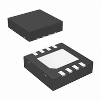
Connection Diagrams www.national.com LD Package Top View Order Number LM4905LD See NS Package Number LDA08A LQ Package 20050802 Top View Order Number LM4905LQ See NS Package Number LQB08A Mini Small Outline (MSOP) Package 20050801 Top View Order Number LM4905MM See ...
Page 3
... Absolute Maximum Ratings If Military/Aerospace specified devices are required, please contact the National Semiconductor Sales Office/ Distributors for availability and specifications. Supply Voltage (Note 10) Storage Temperature Input Voltage Power Dissipation (Notes 3, 11) ESD Susceptibility (Note 4) ESD Susceptibility (Note 5) Junction Temperature Electrical Characteristics V The following specifications apply for the circuit shown in Figure 1, unless otherwise specified ...
Page 4
Electrical Characteristics V The following specifications apply for the circuit shown in Figure 1, unless otherwise specified. Limits apply for T Symbol Parameter I Quiescent Power Supply Current DD I Shutdown Current SD V Shutdown Voltage Input High SDIH V ...
Page 5
External Components Description (Figure 1) Components 1. R Inverting input resistance which sets the closed-loop gain in conjunction with R i high pass filter with Input coupling capacitor which blocks the DC voltage at the amplifiers input ...
Page 6
Typical Performance Characteristics THD+N vs Power Out 3V, 8Ω Power Supply Rejection Ratio (PSRR) vs Frequency 5V, 8Ω Input terminated with 10Ω Power Supply Rejection Ratio (PSRR) vs Frequency at ...
Page 7
Typical Performance Characteristics Power Supply Rejection Ratio (PSRR) vs Frequency 2.6V, 8Ω Input terminated with 10Ω Open Loop Frequency Response, 5V Open Loop Frequency Response, 2.6V (Continued) Power Supply Rejection Ratio (PSRR) vs Frequency L ...
Page 8
Typical Performance Characteristics Power Derating Curves Power Dissipation vs Output Power, V Shutdown Hysteresis Voltage 5V www.national.com (Continued) 20050869 =3V DD 200508C8 200508A1 8 Power Dissipation vs Output Power, 5V, 8Ω 20050897 Power Dissipation vs Output Power, V =2.6V DD ...
Page 9
Typical Performance Characteristics Shutdown Hysteresis Voltage 2.6V Output Power vs Supply Voltage, 16Ω Frequency Response vs Input Capacitor Size (Continued) 200508A5 200508A7 20050854 9 Output Power vs Supply Voltage, 8Ω 200508A6 Output Power vs Supply Voltage, 32Ω 200508A8 www.national.com ...
Page 10
Application Information BRIDGE CONFIGURATION EXPLANATION As shown in Figure 1, the LM4905 has two internal opera- tional amplifiers. The first amplifier’s gain is externally con- figurable, while the second amplifier is internally fixed in a unity-gain, inverting configuration. The closed-loop ...
Page 11
Application Information typical value of 0.1µA. In either case, the shutdown pin should be tied to a definite voltage to avoid unwanted state changes. In many applications, a microcontroller or microprocessor output is used to control the shutdown circuitry, which ...
Page 12
Application Information nates possible high frequency oscillations. Care should be taken when calculating the -3dB frequency in that an incor- rect combination of R and C will cause rolloff before 3 4 www.national.com 20kHz. A typical combination of feedback resistor ...
Page 13
Application Information DIFFERENTIAL AMPLIFIER CONFIGURATION FOR LM4905 (Continued) FIGURE 3. REFERENCE DESIGN BOARD SCHEMATIC FIGURE 4. 13 200508D5 200508D6 www.national.com ...
Page 14
Application Information LM4905 MSOP BOARD ARTWORK Composite View Top Layer Part Description LM4905 Audio AMP Tantalum Capcitor, 1µF Ceramic Capacitor, 0.39µF Resistor, 20kΩ, 1/10W Resistor, 100kΩ, 1/10W Jumper Header Vertical Mount 2X1 0.100“ spacing www.national.com (Continued) 200508E3 200508E5 MONO LM4905 ...
Page 15
Application Information PCB LAYOUT GUIDELINES This section provides practical guidelines for mixed signal PCB layout that involves various digital/analog power and ground traces. Designers should note that these are only "rule-of-thumb" recommendations and the actual results will depend heavily on ...
Page 16
Physical Dimensions www.national.com inches (millimeters) unless otherwise noted LLP Package Order Number LM4905LD NS Package Number LDA08A LLP Package Order Number LM4905LQ NS Package Number LQB08A 16 ...
Page 17
... NATIONAL’S PRODUCTS ARE NOT AUTHORIZED FOR USE AS CRITICAL COMPONENTS IN LIFE SUPPORT DEVICES OR SYSTEMS WITHOUT THE EXPRESS WRITTEN APPROVAL OF THE PRESIDENT AND GENERAL COUNSEL OF NATIONAL SEMICONDUCTOR CORPORATION. As used herein: 1. Life support devices or systems are devices or systems which, (a) are intended for surgical implant ...