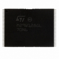
M29W128GL70N6E NUMONYX, M29W128GL70N6E Datasheet - Page 18

M29W128GL70N6E
Manufacturer Part Number
M29W128GL70N6E
Description
IC FLASH 128MBIT 70NS 56TSOP
Manufacturer
NUMONYX
Series
Axcell™r
Datasheet
1.M29W128GH70N6E.pdf
(94 pages)
Specifications of M29W128GL70N6E
Format - Memory
FLASH
Memory Type
FLASH
Memory Size
128M (16Mx8, 8Mx16)
Speed
70ns
Interface
Parallel
Voltage - Supply
2.7 V ~ 3.6 V
Operating Temperature
-40°C ~ 85°C
Package / Case
56-TSOP
Package
56TSOP
Cell Type
NOR
Density
128 Mb
Architecture
Sectored
Block Organization
Symmetrical
Typical Operating Supply Voltage
3|3.3 V
Sector Size
128KByte x 128
Timing Type
Asynchronous
Interface Type
Parallel
Lead Free Status / RoHS Status
Lead free / RoHS Compliant
Available stocks
Company
Part Number
Manufacturer
Quantity
Price
Company:
Part Number:
M29W128GL70N6E
Manufacturer:
MICRON
Quantity:
11 200
Company:
Part Number:
M29W128GL70N6E
Manufacturer:
LATTICE
Quantity:
198
Part Number:
M29W128GL70N6E
Manufacturer:
MICRON
Quantity:
20 000
3.5
3.6
3.7
3.7.1
18/94
Reset
During reset mode the memory is deselected and the outputs are high impedance. The
memory is in reset mode when RP is at V
standby level, independently from the chip enable, output enable or write enable inputs.
Automatic standby
Automatic standby allows the memory to achieve low power consumption during read
mode.
After a read operation, if CMOS levels (V
inactive for t
supply current is reduced to the standby supply current, I
characteristics). The data inputs/outputs will still output data if a bus read operation is in
progress.
The power supplier of data bus, V
circuits connected with data bus) when the memory enters automatic standby.
Auto select mode
The auto select mode allows the system or the programming equipment to read the
electronic signature, verify the protection status of the extended memory block, and
apply/remove block protection. For example, this mode can be used by a programming
equipment to automatically match a device and the application code to be programmed.
There are two methods to enter auto select mode:
At power-up, the device is in read mode, and can then be put in auto select mode by using
one of the methods described above.
The device cannot enter auto select mode when a program or erase operation is ongoing
(RB Low). However, auto select mode can be entered if the erase operation has been
suspended by issuing an Erase Suspend command (see
The auto select mode is exited by performing a reset. The device is returned to read mode,
except if the auto select mode was entered after an Erase Suspend or a Program Suspend
command. In this case, it returns to the erase or program suspend mode.
Read electronic signature
The memory has two codes, the manufacturer code and the device code used to identify the
memory. These codes can be accessed by performing read operations with control signals
and addresses set as shown in
programmer method:
Additional bus operations are used. They require V
Refer to
required to read the electronic signature using the programmer method
in-system method:
The auto select mode is entered by issuing the Auto Select command (see
Section
AVQV
6.1.2). It is not necessary to apply V
Table
+ 30 ns or more, the memory enters automatic standby where the internal
6,
Table
7,
Table
Table 6: Read electronic signature - auto select mode -
CCQ
8, and
, can have a null consumption (depending on load
CC
IL
. The power consumption is reduced to the
± 0.3 V) are used to drive the bus and the bus is
Table 9
ID
to A9.
for a description of the bus operations
ID
CC2
Section
to be applied to address pin A9.
(see
6.1.6).
Table 25: DC


