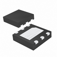
DS2704G+T&R Maxim Integrated Products, DS2704G+T&R Datasheet

DS2704G+T&R
Specifications of DS2704G+T&R
Related parts for DS2704G+T&R
DS2704G+T&R Summary of contents
Page 1
... The 1280-bit memory is organized as 5 pages of 32 bytes each and supports storage of battery cell characteristics, charging voltage, temperature parameters, as well as battery pack manufacturing data. The EEPROM pages are in circuit rewritable and can be individually locked to write protect data ...
Page 2
ABSOLUTE MAXIMUM RATINGS Voltage Range on All Pins, Relative to V Operating Temperature Range Storage Temperature Range Soldering Temperature Stresses beyond those listed under “Absolute Maximum Ratings” may cause permanent damage to the device. These are stress ratings only, and ...
Page 3
AC ELECTRICAL CHARACTERISTICS: 1-WIRE INTERFACE (2.5V ≤ V ≤ 5.5V -30°C to +85°C PARAMETER STANDARD BUS TIMING Time Slot Recovery Time Write 0 Low Time Write 1 Low Time Read Data Valid Reset Time High Reset ...
Page 4
... Figure 1. Block Diagram DETAILED DESCRIPTION The DS2704 is comprised of an EEPROM memory array and SHA-1 Authentication function that are accessed via a 1-Wire interface. The 1-Wire interface controls access by a host system to the 64-bit Net Address (ROM ID), SHA-1 Authentication, 1280-bit EEPROM memory and EEPROM Status. ...
Page 5
... Command and Function Command levels for reading the Memory and Status data fields. Since the DS2704 is based on EEPROM technology versus the EPROM technology used for the DS2502, writing of the Memory and Status data fields is not the same as the DS2502. The DS2704 includes an on-chip charge pump to facilitate in- circuit programming ...
Page 6
Table 1. Authentication Function Commands COMMAND Write Challenge Compute MAC without ROM ID and return MAC Compute MAC with ROM ID and return MAC SECRET MANAGEMENT FUNCTION COMMANDS CLEAR SECRET [5Ah]. This command sets the 64-bit secret to all 0’s ...
Page 7
... The Write Scratchpad, Read Scratchpad and Copy Scratchpad function commands provide write access to the EEPROM data field. The EEPROM memory is organized as 5 pages of 32 bytes each as shown in Table 4. EEPROM Data Field. All pages are read and write (R/W) accessible. When received from the factory, the entire 1280-bit EEPROM data field appears as logical 1’ ...
Page 8
... READ ALL [65h]. The Read All command is used to read data from all 1280 bits (PAGE 0 – PAGE 4) of the EEPROM data field. This includes PAGE 0 – PAGE 3 which are accessible via the DS2502 Read Memory and Read Data/Gen CRC legacy commands and PAGE 4 which is only accessible using the Read All command. ...
Page 9
EEPROM STATUS The DS2704 has a separate 8-byte linear address space for access to the EEPROM Status data field using the Read Status and Write Status Function Commands. READ STATUS [AAh]. The Read Status command is used to read data ...
Page 10
... C3 Generates a CRC value of the data read from each page if read continues to the end of page. 65 Read data from all 5 pages of the EEPROM Memory data field. AA Read data from the 8-byte EEPROM Status data field. 55 Write the Page Protection bits in the EEPROM Status data field. ...
Page 11
... The DS2704 computes an 8-bit CRC for the command and address bytes received from the bus master for the Read Memory, Read Status and Read/Generate CRC commands to confirm that these bytes have been received correctly. The CRC generator on the DS2704 is also used to provide verification of error-free data transfer as each EEPROM page is sent to the master during a Read Data/Generate CRC command and for the 8 bytes of information in the Status memory field ...
Page 12
Figure 4. 1-Wire Bus Interface Circuitry TRANSACTION SEQUENCE The protocol for accessing the DS2704 through the 1-Wire port is as follows: Initialization Net Address Command Function Command(s) Data Transfer (not all commands have data transfer) All transactions of the 1-Wire ...
Page 13
I/O SIGNALING The 1-Wire bus requires strict signaling protocols to ensure data integrity. The four protocols used by the DS2704 are as follows: the initialization sequence (reset pulse followed by presence pulse), write 0, write 1, and read data. The ...
Page 14
Figure 6. 1-Wire Write- and Read-Time Slots DS2704: 1280-Bit EEPROM with SHA-1 Authentication ...
Page 15
... Sets lock bit to prevent changes to the 6A Secret. Read data from 1024-bit EEPROM Memory F0 data field. Read data from 1024-bit EEPROM Memory C3 data field and generate a CRC value of the data read during the operation. Read data from the all 5 pages of the 65 EEPROM Memory data field. ...
Page 16
... Table 8. Guide to Function Command Requirements ISSUE MEMORY COMMAND ADDRESS Write Challenge Compute MAC Compute Next Secret Clear/Lock Secret, Set/Clear Overdrive Read Memory 16 bits: TA1, TA2 Read Data/Gen CRC 16 bits: TA1, TA2 Read All 16 bits: TA1, TA2 Read Status 16 bits Write Status ...
Page 17
Figure 8. Compute Next Secret Function Command Figure 9. Copy Scratchpad Function Command DS2704: 1280-Bit EEPROM with SHA-1 Authentication ...
Page 18
Figure 10. Clear/Lock Secret, Set/Clear Overdrive Function Commands PACKAGE INFORMATION (For the latest package outline information www.maxim-ic.com/DallasPackInfo ...


