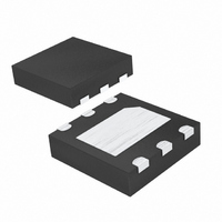
DS2704G+T&R Maxim Integrated Products, DS2704G+T&R Datasheet - Page 4

DS2704G+T&R
Manufacturer Part Number
DS2704G+T&R
Description
IC EEPROM 1.25KBIT 6TDFN
Manufacturer
Maxim Integrated Products
Datasheet
1.DS2704GTR.pdf
(18 pages)
Specifications of DS2704G+T&R
Format - Memory
EEPROMs - Serial
Memory Type
EEPROM
Memory Size
1.25K (32B x 5 pages)
Interface
1-Wire Serial
Voltage - Supply
2.5 V ~ 5.5 V
Operating Temperature
-30°C ~ 85°C
Package / Case
6-TDFN Exposed Pad
Lead Free Status / RoHS Status
Lead free / RoHS Compliant
Speed
-
PIN DESCRIPTION
Figure 1. Block Diagram
DETAILED DESCRIPTION
The DS2704 is comprised of an EEPROM memory array and SHA-1 Authentication function that are accessed via
a 1-Wire interface. The 1-Wire interface controls access by a host system to the 64-bit Net Address (ROM ID),
SHA-1 Authentication, 1280-bit EEPROM memory and EEPROM Status.
The DS2704 operates in one of four modes: standby, communication, computation and programming. Standby
mode is the default mode of operation. Whenever any task has been completed, the IC will automatically return to
standby mode. Standby mode is also directly entered if DQ is low for a period of t
been entered, DQ can be returned to logic high and standby mode is retained. Most operations are performed in
communication mode, with the host system addressing the DS2704 using Net Address commands and then
retrieving EEPROM and Status data using memory function commands or setting up an authentication exchange
and retrieving the results. The supply current, I
selection of Standard or Overdrive bus timing.
2, 3, 4
PIN
6
5
1
SYMBOL
V
DQ
V
NC
SS
DD
Serial interface data I/O pin. Bi-directional data transmit and receive at 16kbps
or 143kbps.
Supply GND and reference for serial communication. Attach V
negative terminal.
Supply input. Bypass to V
No Connection
DD1
, varies depending on bus activity, communication direction, and
SS
4 of 18
with 0.01μF typical.
FUNCTION
RSTL
SS
to battery pack
. Once standby mode has


