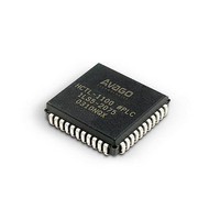
HCTL-1101 Avago Technologies US Inc., HCTL-1101 Datasheet - Page 27

HCTL-1101
Manufacturer Part Number
HCTL-1101
Description
IC MOTION CONTROL GP 40DIP
Manufacturer
Avago Technologies US Inc.
Datasheet
1.HCTL-1101.pdf
(40 pages)
Specifications of HCTL-1101
Applications
DC Motor Controller, Stepper Motor Controller
Voltage - Supply
4.75 V ~ 5.25 V
Operating Temperature
-20°C ~ 85°C
Mounting Type
Through Hole
Package / Case
40-DIP (0.600", 15.24mm)
Lead Free Status / RoHS Status
Lead free / RoHS Compliant
Current - Output
-
Number Of Outputs
-
Voltage - Load
-
Lead Free Status / Rohs Status
Lead free / RoHS Compliant
Available stocks
Company
Part Number
Manufacturer
Quantity
Price
Part Number:
HCTL-1101
Manufacturer:
AVAGO/安华高
Quantity:
20 000
Company:
Part Number:
HCTL-1101-PLC
Manufacturer:
Avago Technologies US Inc.
Quantity:
10 000
Status Register (R07H)
Bit #1- 0 = 3-phase configuration, PHA, PHB, and PHC are
active outputs.
Bit #2- 0 = Rotor position measured in quadrature counts
(4x decoding).
1 = Rotor position measured in full counts (1 count = 1
codewheel bar and space.)
Bit #2 only affects the commutator’s counting method.
This includes the Ring register (R18H), the X and Y regis-
ters (R1AH & R1BH), the Offset register (R1CH), the Velocity
Timer register (R19H), and the Maximum Advance register
(R1FH).
Quadrature counts (4x decoding) are always used by the
HCTL-1101 as a basis for position, velocity, and accelera-
tion control.
Ring Register (R18H)
The Ring register is defined as 1 electrical cycle of the Com-
mutator which corresponds to 1 torque cycle of the mo-
tor. The Ring register is scalar and determines the length
of the commutation cycle measured in full or quadrature
counts as set by bit #2 in the Status register (R07H). The
value of the ring must be limited to the range of 0 to 7FH.
X Register (R1AH)
This register contains scalar data which sets the interval
during which only one phase is active.
Y Register (R1BH)
This register contains scalar data which set the interval
during which two sequential phases are both active. Y is
phase overlap. X and Y must be specified such that:
X + Y = Ring/(# of phases)
These three parameters define the basic electrical com-
mutation cycle.
Offset Register (R1CH)
The Offset register contains two’s-complement data which
determines the relative start of the commutation cycle
with respect to the INDEX pulse. Since the INDEX pulse
must be physically referenced to the rotor, offset performs
fine alignment between the electrical and mechanical
torque cycles.
The Hold Commutator flag (F4) in the Status register
(R07H) is used to decouple the internal commutator
counters from the encoder input. Flag (F4) can be used
in conjunction with the Offset register to allow the user
to advance the commutator phases open loop. This tech-
nique may be used to create a custom commutator align-
ment procedure. For example, in Figure 10, case 1, for a
three-phase motor where the ring = 9, X = 3, and Y = 0,
the phases can be made to advance open loop by setting
27
1 = 4-phase configuration, PHA – PHD are active outputs.
[5]
the Hold Commutator flag (F4) in the Flag register (R07H).
When the values 0, 1, or 2 are written to the Offset reg-
ister, phase A will be enabled. When the values 3, 4 or 5
are written to the Offset register, phase B will be enabled.
And, when the values 6, 7, or 8 are written to the Offset
register, phase C will be enabled. No values larger than the
value programmed into the Ring register should be pro-
grammed into the Offset register.
Phase Advance Registers (R19H, R1FH)
The Velocity Timer register and Maximum Advance regis-
ter linearly increment the phase advance according to the
measured speed for rotation up to a set maximum.
The Velocity Timer register (R19H) contains scalar data
which determines the amount of phase advance at a giv-
en velocity. The phase advance is interpreted in the units
set for the Ring counter by bit #2 in R07H. The velocity is
measured in revolutions per second.
The Maximum Advance register (R1FH) contains scalar
data which sets the upper limit for phase advance regard-
less of rotor speed.
Figure 11 shows the relationship between the Phase Ad-
vance registers. Note: If the phase advance feature is not
used, set both R19H and R1FH to 0.
Commutator Constraints and Use
When choosing a three-channel encoder to use with a DC
brushless or stepper motor, the user should keep in mind
that the number of quadrature encoder counts (4x the
number of slots in the encoder’s codewheel) must be an
integer multiple (1x, 2x, 3x, 4x, 5x, etc.) of the number of
pole pairs in the DC brushless motor or steps in a stepper
motor. To take full advantage of the commutator’s over-
lap feature, the number of quadrature counts should be at
least 3 times the number of pole pairs in the DC brushless
motor or steps in the stepper motor.
For example, a 1.8°, (200 step/revolution) stepper motor
should employ at least a:
150 slot codewheel = 600 quadrature counts/revolution
There are several numerical constraints the user should be
aware of to use the Commutator.
N
v = velocity (revolutions/ second)
F
= full encoder counts/ revolution.
= 3 x 200 steps/revolution.


