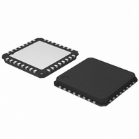
AMIS30623C623BRG ON Semiconductor, AMIS30623C623BRG Datasheet - Page 21

AMIS30623C623BRG
Manufacturer Part Number
AMIS30623C623BRG
Description
IC MOTOR DRIVER/CTLR 32-QFP
Manufacturer
ON Semiconductor
Datasheet
1.AMIS30623C6239RG.pdf
(61 pages)
Specifications of AMIS30623C623BRG
Applications
Stepper Motor Driver
Number Of Outputs
1
Current - Output
800mA
Voltage - Supply
6.5 V ~ 29 V
Operating Temperature
-40°C ~ 165°C
Mounting Type
Surface Mount
Package / Case
32-VSQFP
Mounting Style
SMD/SMT
Lead Free Status / RoHS Status
Lead free / RoHS Compliant
Voltage - Load
-
Lead Free Status / Rohs Status
Lead free / RoHS Compliant
Available stocks
Company
Part Number
Manufacturer
Quantity
Price
Company:
Part Number:
AMIS30623C623BRG
Manufacturer:
ON Semiconductor
Quantity:
1 850
Company:
Part Number:
AMIS30623C623BRG
Manufacturer:
ON Semiconductor
Quantity:
10 000
Main Control and Register, OTP memory + ROM
Power−up Phase
10 ms. After this phase, the AMIS−30623 is in standby
mode, ready to receive LIN messages and execute the
associated commands. After power−up, the registers and
flags are in the reset state, while some of them are being
loaded with the OTP memory content (see Table 19: RAM
Registers).
Reset
micro−cut on pin V
level), the H−bridges will be in high−impedance mode, and
the registers and flags will be in a predetermined position.
This is documented in Table 19: RAM Registers and
Table 20: Flags Table.
Soft−stop
with a deceleration phase. At the end of this action, the
register <TagPos> is loaded with the value contained in
Power−up phase of the AMIS−30623 will not exceed
After power−up, or after a reset occurrence (e.g. a
A soft−stop is an immediate interruption of a motion, but
Figure 13. Simplified Timing Diagram Showing the Change in States for SWI Comparator
SWI_Cmp
“R”−Comp
BB
DriveHS
DriveLS
ActPos
ESW
has made V
R
th
DD
to go below VddReset
Tsw = 1024 ms
0
Tsw_on = 128 ms
120 ms
http://onsemi.com
1
640 ms
21
register <ActPos>, see Table 19: Ram Registers). The
circuit is then ready to execute a new positioning command,
provided thermal and electrical conditions allow for it.
Sleep Mode
driven to its secure position. After which, the circuit is
completely powered down, apart from the LIN receiver,
which remains active to detect a dominant state on the bus.
In case sleep mode is entered while a motion is ongoing, a
transition will occur towards secure position as described in
Positioning and Motion Control provided <SecPos> is
enabled. Otherwise, <SoftStop> is performed.
Sleep mode can be entered in the following cases:
•
•
1
When entering sleep mode, the stepper−motor can be
The circuit receives a LIN frame with identifier 0x3C
and first data byte containing 0x00, as required by LIN
specification rev 1.3 and <SleepEn> bit = 1. See also
Sleep in the LIN Application Command section.
In case the >SleepEn> bit = 1 and the LIN bus remains
inactive (or is lost) during more than 25000 time slots
(1.30 s at 19.2 kbit/s), a time−out signal switches the
circuit to sleep mode.
1
t
t
t
t
t
t


