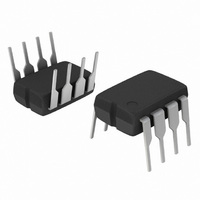
NCP1601BPG ON Semiconductor, NCP1601BPG Datasheet - Page 10

NCP1601BPG
Manufacturer Part Number
NCP1601BPG
Description
IC PFC CTRLR CRM/TRANSITION 8DIP
Manufacturer
ON Semiconductor
Datasheet
1.NCP1601APG.pdf
(19 pages)
Specifications of NCP1601BPG
Mode
Critical Conduction (CRM), Discontinuous (Transition)
Frequency - Switching
58kHz
Current - Startup
17µA
Voltage - Supply
9.6 V ~ 18 V
Operating Temperature
-40°C ~ 125°C
Mounting Type
Through Hole
Package / Case
8-DIP (0.300", 7.62mm)
Start-up Supply Current
17uA
Operating Supply Voltage (min)
-3V
Operating Supply Voltage (max)
18V
Operating Temp Range
-40C to 125C
Operating Temperature Classification
Automotive
Package Type
PDIP
Pin Count
8
Mounting
Through Hole
Switching Frequency
405 KHz
Maximum Operating Temperature
+ 125 C
Mounting Style
Through Hole
Minimum Operating Temperature
- 40 C
Lead Free Status / RoHS Status
Lead free / RoHS Compliant
Other names
NCP1601BPGOS
Available stocks
Company
Part Number
Manufacturer
Quantity
Price
Company:
Part Number:
NCP1601BPG
Manufacturer:
ON Semiconductor
Quantity:
1 500
Part Number:
NCP1601BPG
Manufacturer:
ON/安森美
Quantity:
20 000
Introduction
controller
Conduction Mode (DCM) and Critical Conduction Mode
(CRM). The fixed- - frequency nature of DCM limits the
maximum switching frequency. It limits the possible
conducted and radiated EMI noise that may pollute
surrounding systems. NCP1601 offers the simplest solution
to PFC including fewer external circuit components and
simple voltage- - mode feedback. The diode turn- - off
switching loss is negligible and hence there is no need to
use a low reverse- - recovery time t
hand, the CRM feature is added to limit the maximum
current stress to twice of the average current. The NCP1601
incorporates high safety protection features and combines
the advantages of DCM and CRM so that the NCP1601 is
suitable for robust and compact PFC stages.
The NCP1601 provides the following protection features:
NCP1601A has a typical 4.75 V undervoltage lockout
(UVLO) hysteresis, while NCP1601B has a typical 1.5 V
UVLO hysteresis. It allows the use of different V
schemes.
Operating Modes of NCP1601
operate in fixed- - frequency DCM. In the most stressful
The NCP1601 is a Power Factor Correction (PFC) boost
The NCP1601 is available in two versions. The
The NCP1601 is a PFC driver primarily designed to
1. Overvoltage Protection (OVP) is activated and
2. Undervoltage Protection (UVP) is activated and
3. Overcurrent Protection (OCP) is activated and
4. Thermal Shutdown (TSD) is activated and the
the output drive goes low when the output voltage
exceeds 107% of the nominal regulation level
which is a user- - defined value. The circuit
automatically resumes operation when the output
voltage becomes lower than 107%.
the device is shut down when the output voltage
goes below 8% of the nominal regulation level.
The circuit automatically resumes operation when
the output voltage goes above 8% of the nominal
regulation level. This feature also provides output
open- - loop protection and external shutdown
feature.
the output device goes low when the inductor
current exceeds a user- - defined value. The
operation automatically resumes when the
inductor current becomes lower than this
user- - defined value at the next clock cycle.
output drive is disabled when the junction
temperature exceeds 140C. The operation
resumes when the junction temperature falls
down by typical 45C.
designed
to
operate
rr
diode. On the other
in
Discontinuous
FUNCTIONAL DESCRIPTION
CC
biasing
http://onsemi.com
10
conditions, CRM can be an alternative option which is
without power factor degradation. On the other hand, the
NCP1601 can be viewed as a CRM controller with a
frequency clamp (maximum switching frequency limit)
alternative option which is also without power factor
degradation. In summary, the NCP1601 can cover both
CRM and DCM without power factor degradation. Based
on the selections of the boost inductor and the oscillator
frequency, the circuit is capable of the following three
applications.
CRM in the same averaged input current. Hence, CRM is
generally preferred at around the sinusoidal peak for lower
the maximum current stress but DCM is also preferred at
the non- - peak region to avoid excessive switching
frequencies. Because of the variable- - frequency feature of
the CRM and constant- - frequency feature of DCM,
switching frequency is the maximum in the DCM region
and hence the minimum switching frequency will be found
at the moment of the sinusoidal peak.
DCM PFC Circuit
Input voltage is a rectified 50 or 60 Hz sinusoidal signal. The
MOSFET is switching at a high frequency (typically around
100 kHz) so that the inductor current I
high- - frequency and low- - frequency components.
capacitor in order to eliminate the high- - frequency content
of the DCM inductor current I
DCM needs higher peak inductor current comparing to
A DCM/CRM PFC boost converter is shown in Figure 26.
Filter capacitor C
1. “Mostly in CRM” with a frequency clamp set by
2. “Mostly in fixed- - frequency mode DCM” and
3. “Fixed- - frequency DCM” only.
Current
the oscillator or synchronization frequency.
only run in CRM at high load and low line.
DCM
Figure 25. Operating Modes
Critical Mode
filter
is an essential and very small value
L
. This filter capacitor cannot
Inductor current, I
DCM
L
basically consists of
Input current, I
L
time
in


