IR3088AMTRPBF International Rectifier, IR3088AMTRPBF Datasheet - Page 23
IR3088AMTRPBF
Manufacturer Part Number
IR3088AMTRPBF
Description
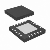
IC XPHASE W/FAULT DET 20L-MLPQ
Manufacturer
International Rectifier
Series
XPhase™r
Datasheet
1.IR3088AMTRPBF.pdf
(33 pages)
Specifications of IR3088AMTRPBF
Applications
Processor
Current - Supply
10mA
Voltage - Supply
8.4 V ~ 14 V
Operating Temperature
0°C ~ 125°C
Mounting Type
Surface Mount
Package / Case
20-MLPQ
Pin Count
20
Mounting
Surface Mount
Package Type
MLPQ
Case Length
4mm
Case Height
0.88mm
Lead Free Status / RoHS Status
Lead free / RoHS Compliant
Other names
IR3088AMTRPBF
IR3088AMTRPBFTR
IR3088AMTRPBFTR
Available stocks
Company
Part Number
Manufacturer
Quantity
Price

Part Number:
IR3088AMTRPBF
Manufacturer:
IR
Quantity:
20 000


Body Braking Related Resistors R
N/A. The body braking during Dynamic VID is disabled.
IR3088A EXTERNAL COMPONENTS
PWM Ramp Resistor R
Set PWM ramp magnitude V
resistor R
Inductor Current Sensing Capacitor C
Choose C
The bias currents of CSIN+ and CSIN- are 0.25uA and 0.4uA respectively. Calculate resistor R
Over Temperature Setting Resistors R
Use central over-temperature setting and set the temperature threshold at 115 ºC, which corresponds to the IC die
temperature of 116 ºC. Calculate the HOTSET threshold voltage corresponding to the temperature thresholds.
Pre-select R
Phase Delay Timing Resistors R
Use central over temperature setting and set the temperature threshold at 115 ºC, which corresponds to the IC die
temperature of 116 ºC. Calculate the HOTSET threshold voltage corresponding to the temperature thresholds.
The phase delay resistor ratios for phases 1 to 6 at 400kHz of switching frequencies are RA
RA
slope. Pre-select R
R
V
R
=
R
R
R
R
HOTSET
PHASE22
PWMRMP
CS
CS
PHASE
HOTSET
12
PHASE2
+
−
Page 23 of 33
∗
=
=
400
12
R
C
L
2
=
CS
CS
=
=
PWMRMP
*
R
=
=7.15k , R
CS+
. 4
=0.415, RA
+
10
1
L
+
V
R
73
−
=
HOTSET1
RA
IN
=
V
3
HOTSET
=47nF, and calculate R
RA
10
∗
*
BIAS
∗
PHASE
220
10
220
0 .
PHASE
f
SW
k
,
−
*
−
Ω
3
1
PHASE11
*
10
1
V
∗
*
∗
10
=10.0k ,
1
PHASE32
C
47
HOTSET
V
T
PHASE3
−
∗
9
J
PWMRMP
−
HOTSET
12
*
R
PWMRMP
/(
+
10
PHASE
. 0
∗
. 1
=R
[ln(
47
−
. 1
241
9
=0.202, RA
PWMRMP
33
=2.55k , R
*
11
=
PHASE21
∗
12
10
[ln(
=
10
=
−
and Capacitor C
−
. 4
6
1
3
. 1
*
PHASE1
V
)
73
8 .
−
10
. 0
IN
35
BBFB
=
CS+,
. 0
−
628
*
=0.8V. Choose 220pF for PWM ramp capacitor C
3
)
10
−
=R
. 1
628
10
−
∗
V
V
79
. 1
PHASE4
CS+
0 .
PHASE42
ln(
HOTSET1
O
DAC
−
PHASE31
3
79
and R
k
and R
∗
12
Ω
∗
10
)
and Resistors R
116
=
−
−
*
. 3
ln(
. 1
10
=0.246, RA
BBDRP
+
57
PHASE2
35
=3.24k , P
=R
V
3
and R
. 1
PWMRMP
IN
k
=
−
241
Ω
PHASE41
16
0
−
8 .
V
9 .
=
)]
DAC
HOTSET2
k
. 1
Ω
=
79
PHASE5
16
−
PHASE52
=R
V
V
.
CS+
k 1
PWMRMP
PHASE51
Ω
and R
=0.441 and RA
, choose R
=7.87k , R
)]
= R
CS-
PHASE61
PWMRMP
PHASE62
PHASE6
=10k ,
=16.2k
IR3088APbF
=17.4k
PWMRMP
=0.637 starting from down-
May 18, 2009
CS-
, and calculate the
,
PHASE1
=0.628,
Related parts for IR3088AMTRPBF
Image
Part Number
Description
Manufacturer
Datasheet
Request
R

Part Number:
Description:
XPHASETM PHASE IC WITH FAULT AND OVERTEMP DETECT
Manufacturer:
IRF [International Rectifier]
Datasheet:

Part Number:
Description:
Xphase Ic With Fault And Overtemp Detect
Manufacturer:
International Rectifier Corp.
Datasheet:
Part Number:
Description:
SCHOTTKY RECTIFIER
Manufacturer:
International Rectifier Corp.
Datasheet:
Part Number:
Description:
SCHOTTKY RECTIFIER
Manufacturer:
International Rectifier Corp.
Datasheet:
Part Number:
Description:
SCHOTTKY RECTIFIER
Manufacturer:
International Rectifier Corp.
Datasheet:
Part Number:
Description:
SCHOTTKY RECTIFIER
Manufacturer:
International Rectifier Corp.
Datasheet:
Part Number:
Description:
SCHOTTKY RECTIFIER
Manufacturer:
International Rectifier Corp.
Datasheet:
Part Number:
Description:
SCHOTTKY RECTIFIER
Manufacturer:
International Rectifier Corp.
Datasheet:
Part Number:
Description:
SCHOTTKY RECTIFIER
Manufacturer:
International Rectifier Corp.
Datasheet:
Part Number:
Description:
SCHOTTKY RECTIFIER
Manufacturer:
International Rectifier Corp.
Datasheet:
Part Number:
Description:
SCHOTTKY RECTIFIER
Manufacturer:
International Rectifier Corp.
Datasheet:
Part Number:
Description:
SCHOTTKY RECTIFIER
Manufacturer:
International Rectifier Corp.
Datasheet:
Part Number:
Description:
SCHOTTKY RECTIFIER
Manufacturer:
International Rectifier Corp.
Datasheet:
Part Number:
Description:
SCHOTTKY RECTIFIER
Manufacturer:
International Rectifier Corp.
Datasheet:
Part Number:
Description:
SCHOTTKY RECTIFIER
Manufacturer:
International Rectifier Corp.
Datasheet: