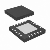
IR3088AMTRPBF International Rectifier, IR3088AMTRPBF Datasheet - Page 5

IR3088AMTRPBF
Manufacturer Part Number
IR3088AMTRPBF
Description
IC XPHASE W/FAULT DET 20L-MLPQ
Manufacturer
International Rectifier
Series
XPhase™r
Datasheet
1.IR3088AMTRPBF.pdf
(33 pages)
Specifications of IR3088AMTRPBF
Applications
Processor
Current - Supply
10mA
Voltage - Supply
8.4 V ~ 14 V
Operating Temperature
0°C ~ 125°C
Mounting Type
Surface Mount
Package / Case
20-MLPQ
Pin Count
20
Mounting
Surface Mount
Package Type
MLPQ
Case Length
4mm
Case Height
0.88mm
Lead Free Status / RoHS Status
Lead free / RoHS Compliant
Other names
IR3088AMTRPBF
IR3088AMTRPBFTR
IR3088AMTRPBFTR
Available stocks
Company
Part Number
Manufacturer
Quantity
Price
Part Number:
IR3088AMTRPBF
Manufacturer:
IR
Quantity:
20 000
Note 1: Guaranteed by design, but not tested in production
PIN DESCRIPTION
Page 5 of 33
General
VCC Supply Current
VCCL Supply Current
VCCH Supply Current
BIASIN Bias Current
DACIN Bias Current
PIN#
10
11
12
13
14
15
16
17
18
19
20
1
2
3
4
5
6
7
8
9
PARAMETER
PIN SYMBOL
PWMRMP
HOTSET
RMPIN+
PHSFLT
ISHARE
RMPIN-
SCOMP
VRHOT
GATEH
GATEL
BIASIN
DACIN
CSIN+
PGND
LGND
VCCH
CSIN-
VCCL
EAIN
VCC
PIN DESCRIPTION
Non-inverting input to Ramp Comparator
Inverting input to Ramp Comparator
Inverting input to VRHOT comparator. Connect resistor divider from VBIAS to LGND
to program VRHOT threshold. Diode or thermistor may be substituted for lower
resistor for enhanced/remote temperature sensing.
Open Collector output of the VRHOT comparator which drives low if IC junction
temperature exceeds the user programmable limit. Connect external pull-up.
Output of the Current Sense Amplifier and input to the Share Adjust Error Amplifier.
Voltage on this pin is equal to V(DACIN) + 34 * [V(CSIN+) – V(CSIN-)]. Connecting
ISHARE pins together creates a Share Bus enabling current sharing between Phase
ICs. The Share bus is also used by the Control IC for voltage positioning and Over-
Current protection.
Compensation for the Current Share control loop. Connect a capacitor to ground to
set the control loop’s bandwidth.
PWM comparator input from the error amplifier output of Control IC. Both Gate
Driver outputs drive low if the voltage on this pin is less than 91% of V(DACIN).
PWM comparator ramp input. Connect a resistor from this pin to the converter input
voltage and a capacitor to LGND to program the PWM ramp.
Signal ground and IC substrate connection
Power for internal circuitry
Power for Low-Side Gate Driver
Low-Side Gate Driver Output and input to GATEH non-overlap comparator
Return for Gate Drivers
High-Side Gate Driver Output and input to GATEL non-overlap comparator
Power for High-Side Gate Driver
Non-inverting input to the Current Sense Amplifier
Inverting input to the Current Sense
Open Collector output of the Phase Fault comparator. Drives low if Phase current is
unable to match the level of the SHARE bus due to an external fault. Connect
external pull-up.
Reference voltage input from the Control IC. Current sensing and PWM operation
referenced to this pin.
System reference voltage for internal circuitry
6V ≤ V
14V ≤ V
CCH
CCH
TEST CONDITION
≤ 14V
≤ 25V
MIN
-5
-2
IR3088APbF
TYP
-2.5
-0.5
2.5
5.5
6.5
May 18, 2009
10
MAX
14
10
5
8
2
1
UNIT
mA
mA
mA
mA
µA
µA


