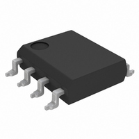
LM75AIM/NOPB National Semiconductor, LM75AIM/NOPB Datasheet - Page 5

LM75AIM/NOPB
Manufacturer Part Number
LM75AIM/NOPB
Description
IC TEMP SENSOR WATCHDOG 8-SOIC
Manufacturer
National Semiconductor
Datasheet
1.LM75AIMNOPB.pdf
(18 pages)
Specifications of LM75AIM/NOPB
Function
Temp Sensor, Watchdog
Topology
ADC (Sigma Delta), Comparator, Register Bank
Sensor Type
Internal
Sensing Temperature
-55°C ~ 125°C
Output Type
I²C™
Output Alarm
Yes
Output Fan
Yes
Voltage - Supply
2.7 V ~ 5.5 V
Operating Temperature
-55°C ~ 125°C
Mounting Type
Surface Mount
Package / Case
8-SOIC (3.9mm Width)
For Use With
OM6285 - EVAL BOARD I2C-2002-1A568-4002 - DEMO BOARD I2C
Lead Free Status / RoHS Status
Lead free / RoHS Compliant
Other names
LM75AIM
t
t
t
t
t
t
V
V
I
I
C
I
V
t
1
2
3
4
5
TIMEOUT
IN(1)
IN(0)
OH
OF
Symbol
Symbol
IN(1)
IN(0)
OL
IN
Logic Electrical Characteristics
DIGITAL DC CHARACTERISTICS
Unless otherwise noted, these specifications apply for +V
LM75BIMM-5, LM75CIM-5, and LM75CIMM-5; and +V
(Note 6). Boldface limits apply for T
I
Unless otherwise noted, these specifications apply for +V
LM75BIMM-5, LM75CIM-5, and LM75CIMM-5; and +V
LM75CIMM-3C
T
The switching characteristics of the LM75 fully meet or exceed the published specifications of the I
are the timing relationships between SCL and SDA signals related to the LM75. They are not the I
2
MIN
C DIGITAL SWITCHING CHARACTERISTICS
to T
MAX
SCL (Clock) Period
Data in Set-Up Time to SCL High
Data Out Stable after SCL Low
SDA Low Set-Up Time to SCL Low (Start Condition)
SDA High Hold Time after SCL High (Stop Condition)
SDA Time Low for Reset of Serial Interface (Note 13)
Logical “1” Input Voltage
Logical “0” Input Voltage
Logical “1” Input Current
Logical “0” Input Current
All Digital Inputs
High Level Output Current
Low Level Output Voltage
Output Fall Time
; all other limits T
L
(load capacitance) on output lines = 80 pF unless otherwise specified. Boldface limits apply for T
Parameter
A
= T
J
= +25°C, unless otherwise noted.
Parameter
A
= T
J
LM75A
LM75B
LM75C
= T
MIN
to T
S
S
= +3.3 Vdc for LM75BIM-3, LM75BIMM-3, LM75CIM-3, and LM75CIMM-3
MAX
= +3.3 Vdc for LM75BIM-3, LM75BIMM-3, LM75CIM-3, and
S
V
V
V
V
V
I
C
I
S
OL
O
IN
IN
OH
OH
OH
L
= +2.7 to 5.5 Vdc for LM75AIM, +V
; all other limits T
= +2.7 to 5.5 Vdc for LM75AIM and V
= 3 mA
Conditions
= 400 pF
= 3 mA
= +V
= 0V
= 5V
= 5V
= 5V
5
S
LM75A,
LM75B
LM75C
A
= T
Conditions
(Note 12)
Typical
J
−0.005
0.005
= +25°C, unless otherwise noted.
5
(Note 12)
Typical
S
= +5 Vdc for LM75BIM-5,
2
S
C bus. The following parameters
2
= +5 Vdc for LM75BIM-5,
C bus specifications.
+V
+V
+V
(Note 7)
Limits
−0.3
−1.0
S
S
S
100
250
1.0
0.4
10
1
× 0.7
+ 0.3
× 0.3
(Note 7)
Limits
100
100
100
325
2.5
75
0
Not Applicable
A
www.national.com
= T
μA (max)
μA (max)
μA (max)
μA (max)
μA (max)
ns (max)
V (max)
V (max)
V (max)
V (min)
V (min)
(Limit)
Units
ms (max)
ms (min)
μs (min)
ns (min)
ns (min)
ns (min)
ns (min)
J
pF
(Limit)
Units
=


