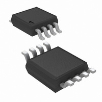
LM75BIMM-5/NOPB National Semiconductor, LM75BIMM-5/NOPB Datasheet - Page 9

LM75BIMM-5/NOPB
Manufacturer Part Number
LM75BIMM-5/NOPB
Description
IC TEMP SENSOR DGTL 8-MSOP
Manufacturer
National Semiconductor
Datasheet
1.LM75AIMNOPB.pdf
(18 pages)
Specifications of LM75BIMM-5/NOPB
Function
Temp Sensor, Watchdog
Topology
ADC (Sigma Delta), Comparator, Register Bank
Sensor Type
Internal
Sensing Temperature
-55°C ~ 125°C
Output Type
I²C™
Output Alarm
Yes
Output Fan
Yes
Voltage - Supply
3 V ~ 5.5 V
Operating Temperature
-55°C ~ 125°C
Mounting Type
Surface Mount
Package / Case
8-MSOP, Micro8™, 8-uMAX, 8-uSOP,
Lead Free Status / RoHS Status
Lead free / RoHS Compliant
Other names
LM75BIMM-5
Available stocks
Company
Part Number
Manufacturer
Quantity
Price
Company:
Part Number:
LM75BIMM-5/NOPB
Manufacturer:
TI/NS
Quantity:
10 000
Part Number:
LM75BIMM-5/NOPB
Manufacturer:
NS/国半
Quantity:
20 000
1.0 Functional Description
The LM75 temperature sensor incorporates a band-gap type
temperature sensor and 9-bit ADC (Sigma-Delta Analog-to-
Digital Converter). The temperature data output of the LM75
is available at all times via the I
progress, it will be stopped and restarted after the read. A
digital comparator is also incorporated that compares a series
of readings, the number of which is user-selectable, to user-
programmable setpoint and hysteresis values. The compara-
tor trips the O.S. output line, which is programmable for mode
and polarity.
The LM75A and LM75B contain all the functionality of the
LM75C, plus two additional features:
1.
2.
1.1 O.S. OUTPUT, T
In Comparator mode the O.S. Output behaves like a thermo-
stat. The output becomes active when temperature exceeds
the T
ture drops below the T
can be used to turn a cooling fan on, initiate an emergency
system shutdown, or reduce system clock speed. Shutdown
mode does not reset O.S. state in a comparator mode.
In Interrupt mode exceeding T
O.S. will remain active indefinitely until reset by reading any
register via the I
by crossing T
Temperature going below T
indefinitely until being reset by a read. Placing the LM75 in
shutdown mode also resets the O.S. Output.
The LM75A and LM75B have an integrated low-pass
filter on both the SDA and the SCL line. These filters
increase communications reliability in noisy
environments.
The LM75A and LM75B also have a bus fault timeout
feature. If the SDA line is held low for longer than
t
reset to the IDLE state (SDA set to high impedance) and
wait for a new start condition. The TIMEOUT feature is
not functional in Shutdown Mode.
TIMEOUT
OS
limit, and leaves the active state when the tempera-
(see specification) the LM75A and LM75B will
OS
, then reset, it can be activated again only by
2
C interface. Once O.S. has been activated
OS
HYST
AND T
limit. In this mode the O.S. output
HYST
OS
HYST
2
. Again, it will remain active
C bus. If a conversion is in
also makes O.S. active but
LIMITS
9
1.2 POWER UP AND POWER DOWN
The LM75 always powers up in a known state. The power up
default conditions are:
1.
2.
3.
4.
5.
When the supply voltage is less than about 1.7V, the LM75 is
considered powered down. As the supply voltage rises above
the nominal 1.7V power up threshold, the internal registers
are reset to the power up default values listed above.
1.2.1 Stand-Alone Thermostat Mode
If the LM75 is not connected to the I
act as a stand-alone thermostat with the power up default
conditions listed above. It is optional, but recommended, to
connect the address pins (A2, A1, A0) and the SCL and SDA
pins together and to a 10k pull-up resistor to +V
noise immunity. Any of these pins may also be tied high sep-
arately through a 10k pull-up resistor.
1.3 I
The LM75 operates as a slave on the I
is an input (no clock is generated by the LM75) and the SDA
line is a bi-directional serial data path. According to I
specifications, the LM75 has a 7-bit slave address. The four
most significant bits of the slave address are hard wired inside
the LM75 and are “1001”. The three least significant bits of
the address are assigned to pins A2–A0, and are set by con-
necting these pins to ground for a low, (0); or to +V
(1).
Therefore, the complete slave address is:
MSB
1
2
Comparator mode
T
T
O.S. active low
Pointer = “00”
C BUS INTERFACE
OS
HYST
= 80°C
= 75°C
0
0
1
2
C bus on power up, it will
A2
2
C bus, so the SCL line
A1
www.national.com
S
S
for a high,
for better
LSB
2
A0
C bus


