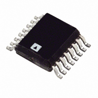
ADT7316ARQ-REEL7 Analog Devices Inc, ADT7316ARQ-REEL7 Datasheet - Page 24

ADT7316ARQ-REEL7
Manufacturer Part Number
ADT7316ARQ-REEL7
Description
IC SENSOR TEMP 12BIT DAC 16QSOP
Manufacturer
Analog Devices Inc
Datasheet
1.ADT7316ARQ.pdf
(44 pages)
Specifications of ADT7316ARQ-REEL7
Rohs Status
RoHS non-compliant
Function
Temp Monitoring System (Sensor)
Topology
ADC, Comparator, Multiplexer, Register Bank
Sensor Type
External & Internal
Sensing Temperature
-40°C ~ 120°C, External Sensor
Output Type
I²C™, MICROWIRE™, QSPI™, SMBus™, SPI™
Output Alarm
No
Output Fan
No
Voltage - Supply
2.7 V ~ 5.5 V
Operating Temperature
-40°C ~ 120°C
Mounting Type
Surface Mount
Package / Case
16-QSOP
For Use With
EVAL-ADT7316EBZ - BOARD EVAL FOR ADT7316
Lead Free Status / RoHS Status
Not Compliant
ADT7316/ADT7317/ADT7318
Table 8. V
V
2.5
3.0
3.5
4.0
4.5
5.0
5.5
6.0
6.5
7.0
ON-CHIP REFERENCE
The ADT7316/ADT7317/ADT7318 have an on-chip 1.2 V band
gap reference that is gained up by a switched capacitor amplifier
to give an output of 2.28 V. The amplifier is powered up for the
duration of the device monitoring phase and is powered down
once monitoring is disabled. This saves on current consump-
tion. The internal reference is used as the reference for the
ADC. The ADC is used for measuring V
and external temperature sensors. The internal reference is
always used when measuring V
nal temperature sensors. The external reference is the default
power-up reference for the DACs.
ROUND ROBIN MEASUREMENT
On power-up, the ADT7316/ADT7317/ADT7318 go into round
robin mode, but monitoring is disabled. Setting Bit C0 of the
Configuration 1 Register (Address 0x18) to 1 enables conversions.
It sequences through the three channels of V
temperature sensor, and the external temperature sensor and
takes a measurement from each. Once the conversion is completed
on the external temperature sensor, the device loops around for
another measurement cycle on all three channels. (This method
of taking a measurement on all three channels in one cycle is
called round robin.) Setting Bit 4 of the Control Configura-
tion 2 register (Address 0x19) disables the round-robin mode
and in turn sets up the single-channel mode. The single-channel
mode is where only one channel (for example, the internal tem-
perature sensor) is measured in each conversion cycle.
The time taken to monitor all channels is typically not of
interest, because the most recently measured value can be
read at any time.
For applications where the round-robin time is important,
typical times at 25°C are given in the Specifications section.
DD
Value (V)
DD
Data Format, V
Binary
01 0110 1110
01 1011 0111
10 0000 0000
10 0100 1001
10 1001 0010
10 1101 1100
11 0010 0101
11 0110 1110
11 1011 0111
11 1111 1111
REF
DD
= 2.28 V
, and the internal and exter-
Digital Output
DD
and the internal
DD
, the internal
Hex
16E
1B7
200
249
292
2DC
325
36E
3B7
3FF
Rev. B | Page 24 of 44
SINGLE-CHANNEL MEASUREMENT
Setting C4 of the Control Configuration 2 register (Address
0x19) enables the single-channel mode and allows the ADT7316/
ADT7317/ ADT7318 to focus on one channel only. A channel
is selected by writing to Bit C0 and Bit C1 in the Control Con-
figuration 2 register. For example, to select the V
monitoring, write to the Control Configuration 2 register and
set C4 = 1 (if this has not been done), then write all 0s to Bit C0
to Bit C1. All subsequent conversions are done on the V
only. To change the channel selection to the internal tempera-
ture channel, write to the Control Configuration 2 register and
set C0 = 1. When measuring in single-channel mode, conversions
on the channel selected occur directly after each other. Any
communication to the ADT7316/ADT7317/ ADT7318 stops
the conversions, but they are restarted once the read or write
operation is completed.
TEMPERATURE MEASUREMENT METHOD
Internal Temperature Measurement
The ADT7316/ADT7317/ADT7318 contain an on-chip, band
gap temperature sensor whose output is digitized by the on-chip
ADC. The temperature data is stored in the internal temperature
value register. As both positive and negative temperatures can
be measured, the temperature data is stored in twos comple-
ment format, as shown in Table 9. The thermal characteristics
of the measurement sensor can change, and therefore an offset
is added to the measured value to enable the transfer function
to match the thermal characteristics. This offset is added before
the temperature data is stored. The offset value used is stored in
the internal temperature offset register.
External Temperature Measurement
The ADT7316/ADT7317/ADT7318 can measure the tempera-
ture of one external diode sensor or diode-connected transistor.
The forward voltage of a diode or diode-connected transistor,
operated at a constant current, exhibits a negative temperature
coefficient of about –2 mV/°C. Unfortunately, the absolute value
of V
required to null this out, so the technique is unsuitable for mass
production.
TRANSISTOR
BE
INTERNAL
SENSE
Figure 44. Top Level Structure of Internal Temperature Sensors
varies from device to device, and individual calibration is
I
N × I
DIODE
BIAS
I
BIAS
V
DD
DD
channel for
TO ADC
V
V
DD
OUT+
OUT–
channel


