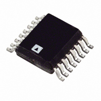
ADT7316ARQ-REEL7 Analog Devices Inc, ADT7316ARQ-REEL7 Datasheet - Page 25

ADT7316ARQ-REEL7
Manufacturer Part Number
ADT7316ARQ-REEL7
Description
IC SENSOR TEMP 12BIT DAC 16QSOP
Manufacturer
Analog Devices Inc
Datasheet
1.ADT7316ARQ.pdf
(44 pages)
Specifications of ADT7316ARQ-REEL7
Rohs Status
RoHS non-compliant
Function
Temp Monitoring System (Sensor)
Topology
ADC, Comparator, Multiplexer, Register Bank
Sensor Type
External & Internal
Sensing Temperature
-40°C ~ 120°C, External Sensor
Output Type
I²C™, MICROWIRE™, QSPI™, SMBus™, SPI™
Output Alarm
No
Output Fan
No
Voltage - Supply
2.7 V ~ 5.5 V
Operating Temperature
-40°C ~ 120°C
Mounting Type
Surface Mount
Package / Case
16-QSOP
For Use With
EVAL-ADT7316EBZ - BOARD EVAL FOR ADT7316
Lead Free Status / RoHS Status
Not Compliant
The technique used in the ADT7316/ADT7317/ADT7318 is to
measure the change in V
different currents. This is given by
where:
K is Boltzmann’s constant.
q is the charge on the carrier.
T is the absolute temperature in Kelvin.
N is the ratio of the two currents.
Figure 41 shows the input signal conditioning used to measure
the output of an external temperature sensor. This figure shows
the external sensor as a discrete substrate transistor. If a PNP
transistor is used, the base is connected to the D− input and the
emitter to the D+ input. If an NPN transistor is used, the emitter is
connected to the D− input and the base to the D+ input.
A 2N3906 is recommended to be used as the external transistor.
To prevent ground noise interfering with the measurement, the
more negative terminal of the sensor is not referenced to ground,
but is biased above ground by an internal diode at the D− input.
As the sensor is operating in a noisy environment, C1 is pro-
vided as a noise filter. See the Layout Considerations section on
for more information on C1.
To measure ΔV
currents of I and N × I. The resulting waveform is passed
through a low-pass filter to remove noise, then to a chopper
stabilized amplifier that performs the functions of amplification
and rectification of the waveform to produce a dc voltage pro-
portional to ΔV
a temperature output in 10-bit twos complement format. To
further reduce the effects of noise, digital filtering is performed
by averaging the results of 16 measurement cycles.
ΔV
BE
= KT/q × ln (N)
BE
BE
, the sensor is switched between operating
. This voltage is measured by the ADC to give
BE
when the device is operated at two
Rev. B | Page 25 of 44
TEMPERATURE VALUE FORMAT
One LSB of the ADC corresponds to 0.25°C. The ADC can theo-
retically measure a temperature span of 255°C. The internal
temperature sensor is guaranteed to a low value limit of −40°C.
It is possible to measure the full temperature span using the
external temperature sensor. The temperature data format is
shown in Table 9. The result of the internal or external tempera-
ture measurements is stored in the temperature value registers
and is compared with limits programmed into the internal or
external high and low registers.
Table 9. Temperature Data Format (Internal and External
Temperature)
−40°C
−25°C
−10°C
−0.25°C
0°C
0.25°C
10°C
25°C
50°C
75°C
100°C
105°C
125°C
Temperature Conversion Formula
where DB9 is removed from the ADC code in the Negative
Temperature equation.
Temperature
Positive Temperature = ADC Code/4
Negative Temperature = (ADC Code − 512)/4
ADT7316/ADT7317/ADT7318
Digital Output
11 0110 0000
11 1001 1100
11 1101 1000
11 1111 1111
00 0000 0000
00 0000 0001
00 0010 1000
00 0110 0100
00 1100 1000
01 0010 1100
01 1001 0000
01 1010 0100
01 1111 0100
DB9..........DB0


