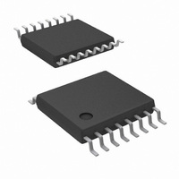
LM5025AMTC/NOPB National Semiconductor, LM5025AMTC/NOPB Datasheet - Page 10

LM5025AMTC/NOPB
Manufacturer Part Number
LM5025AMTC/NOPB
Description
IC CTRLR PWM CLAMP VOLT 16TSSOP
Manufacturer
National Semiconductor
Series
PowerWise®r
Specifications of LM5025AMTC/NOPB
Pwm Type
Voltage Mode
Number Of Outputs
2
Frequency - Max
1MHz
Duty Cycle
92.5%
Voltage - Supply
13 V ~ 90 V
Buck
Yes
Boost
Yes
Flyback
Yes
Inverting
Yes
Doubler
No
Divider
No
Cuk
No
Isolated
Yes
Operating Temperature
-40°C ~ 125°C
Package / Case
16-TSSOP
Frequency-max
1MHz
Number Of Pwm Outputs
2
On/off Pin
No
Adjustable Output
No
Topology
Forward
Switching Freq
220KHz
Output Current
3000/1000A
Synchronous Pin
Yes
Rise Time
20ns
Fall Time
15ns
Operating Temperature Classification
Automotive
Mounting
Surface Mount
Pin Count
16
Package Type
TSSOP
For Use With
LM5025AEVAL - BOARD EVALUATION LM5025ALM5025EVAL - EVALUATION BOARD FOR LM5025
Lead Free Status / RoHS Status
Lead free / RoHS Compliant
Other names
*LM5025AMTC
*LM5025AMTC/NOPB
LM5025AMTC
*LM5025AMTC/NOPB
LM5025AMTC
Available stocks
Company
Part Number
Manufacturer
Quantity
Price
Part Number:
LM5025AMTC/NOPB
Manufacturer:
TI/德州仪器
Quantity:
20 000
www.national.com
Compound Gate Drivers
The LM5025A contains two unique compound gate drivers,
which parallel both MOS and Bipolar devices to provide high
drive current throughout the entire switching event. The Bipo-
lar device provides most of the drive current capability and
provides a relatively constant sink current which is ideal for
driving large power MOSFETs. As the switching event nears
conclusion and the Bipolar device saturates, the internal MOS
device continues to provide a low impedance to compete the
switching event.
During turn-off at the Miller plateau region, typically around
2V - 3V, is where gate driver current capability is needed
most. The resistive characteristics of all MOS gate drivers are
adequate for turn-on since the supply to output voltage dif-
ferential is fairly large at the Miller region. During turn-off
however, the voltage differential is small and the current
source characteristic of the Bipolar gate driver is beneficial to
provide fast drive capability.
PWM Comparator
The PWM comparator compares the ramp signal (RAMP) to
the loop error signal (COMP). This comparator is optimized
for speed in order to achieve minimum controllable duty cy-
cles. The internal 5kΩ pull-up resistor, connected between
the internal 5V reference and COMP, can be used as the pull-
20107413
FIGURE 1.
10
up for an optocoupler. The comparator polarity is such that
0V on the COMP pin will produce a zero duty cycle on both
gate driver outputs.
Volt Second Clamp
The Volt x Second Clamp comparator compares the ramp
signal (RAMP) to a fixed 2.5V reference. By proper selection
of RFF and CFF, the maximum ON time of the main switch
can be set to the desired duration. The ON time set by Volt x
Second Clamp varies inversely with the line voltage because
the RAMP capacitor is charged by a resistor connected to Vin
while the threshold of the clamp is a fixed voltage (2.5V). An
example will illustrate the use of the Volt x Second Clamp
comparator to achieve a 50% duty cycle limit, at 200KHz, at
a 48V line input: A 50% duty cycle at a 200KHz requires a
2.5µs of ON time. At 48V input the Volt x Second product is
120V x µs (48V x 2.5µs). To achieve this clamp level:
Select C
R
The recommended capacitor value range for CFF is 100pF to
1000pF.
The C
every cycle by an internal discharge switch controlled by ei-
ther the internal clock or by the V x S Clamp comparator,
whichever event occurs first.
Current Limit
The LM5025A contains two modes of over-current protection.
If the sense voltage at the CS1 input exceeds 0.5V the present
power cycle is terminated (cycle-by-cycle current limit). If the
sense voltage at the CS2 input exceeds 0.5V, the controller
will terminate the present cycle, discharge the softstart ca-
pacitor and reduce the softstart current source to 1µA. The
softstart (SS) capacitor is released after being fully dis-
charged and slowly charges with a 1µA current source. When
the voltage at the SS pin reaches approximately 1V, the PWM
comparator will produce the first output pulse at OUT_A. After
the first pulse occurs, the softstart current source will revert
to the normal 20µA level. Fully discharging and then slowly
FF
= 102kΩ
FF
FF
ramp capacitor is discharged at the conclusion of
= 470pF
R
FF
48 x 2.5µ / 2.5 = 48µ
x C
FF
= V
IN
x T
ON
20107412
/ 2.5V


