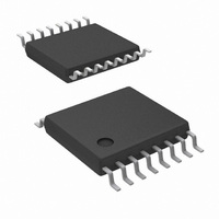
LM5041MTC/NOPB National Semiconductor, LM5041MTC/NOPB Datasheet - Page 3

LM5041MTC/NOPB
Manufacturer Part Number
LM5041MTC/NOPB
Description
IC CTRLR PWM CASCADED 16-TSSOP
Manufacturer
National Semiconductor
Series
PowerWise®r
Datasheet
1.LM5041MTCNOPB.pdf
(16 pages)
Specifications of LM5041MTC/NOPB
Pwm Type
Current Mode
Number Of Outputs
1
Frequency - Max
1MHz
Duty Cycle
91%
Voltage - Supply
15 V ~ 90 V
Buck
Yes
Boost
Yes
Flyback
No
Inverting
Yes
Doubler
No
Divider
No
Cuk
No
Isolated
Yes
Operating Temperature
-40°C ~ 125°C
Package / Case
16-TSSOP
Frequency-max
1MHz
Number Of Pwm Outputs
1
On/off Pin
Yes
Adjustable Output
Yes
Switching Freq
600KHz
Operating Supply Voltage (max)
9.3V
Output Current
1.5A
Synchronous Pin
Yes
Rise Time
20ns
Fall Time
20ns
Operating Temperature Classification
Automotive
Mounting
Surface Mount
Pin Count
16
Package Type
TSSOP
For Use With
LM5041EVAL - BOARD EVALUATION LM5041
Lead Free Status / RoHS Status
Lead free / RoHS Compliant
Other names
*LM5041MTC
*LM5041MTC/NOPB
LM5041MTC
*LM5041MTC/NOPB
LM5041MTC
Pin Description
DAP
LLP
PIN
10
11
12
13
14
15
16
9
RT / SYNC
NAME
PGND
AGND
UVLO
PULL
TIME
SUB
CS
SS
Output of the push-pull drivers
Power ground
Analog ground
Current sense input
Soft-start control
Push-Pull overlap and dead time control
Oscillator timing resistor pin and sync
Line Under-Voltage Shutdown
Die substrate
(Continued)
DESCRIPTION
3
Output of the push-pull gate driver. Output capability
of 1.5A peak.
Connect directly to analog ground.
Connect directly to power ground.
Current sense input to the PWM comparator (CM
control). There is a 50ns leading edge blanking on
this pin. Using separate dedicated comparators, if
CS exceeds 0.5V the outputs will go into cycle by
cycle current limit. If CS exceeds 0.6V the outputs
will be disabled and a soft-start commenced.
An external capacitor and an internal 10uA current
source, set the soft-start ramp. The controller will
enter a low power state if the SS pin is below the
shutdown threshold of 0.45V
An external resistor (R
dead time for the push-pull outputs. A resistor
connected between TIME and GND produces
overlap. A resistor connected between TIME and
REF produces dead time.
An external resistor sets the oscillator frequency.
This pin will also accept an external oscillator.
An external divider from the power converter source
sets the shutdown levels. Threshold of operation
equals 2.5V. Hysteresis is set by a switched internal
current source (20µA).
The exposed die attach pad on the LLP package
should be connected to a PCB thermal pad at
ground potential. For additional information on using
National Semiconductor’s No Pull Back LLP
package, please refer to LLP Application Note
AN-1187.
APPLICATION INFORMATION
SET
) sets the overlap time or
www.national.com


