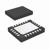
LM5035ASQX/NOPB National Semiconductor, LM5035ASQX/NOPB Datasheet - Page 3

LM5035ASQX/NOPB
Manufacturer Part Number
LM5035ASQX/NOPB
Description
IC PWM BUCK BST FLYBCK INV 24LLP
Manufacturer
National Semiconductor
Series
PowerWise®r
Datasheet
1.LM5035SQNOPB.pdf
(28 pages)
Specifications of LM5035ASQX/NOPB
Pwm Type
Voltage Mode
Number Of Outputs
1
Frequency - Max
1MHz
Duty Cycle
92%
Voltage - Supply
13 V ~ 105 V
Buck
Yes
Boost
Yes
Flyback
Yes
Inverting
Yes
Doubler
No
Divider
No
Cuk
No
Isolated
Yes
Operating Temperature
-40°C ~ 125°C
Package / Case
24-LLP
Frequency-max
1MHz
For Use With
LM5035AEVAL - BOARD EVAL FOR LM5035ALM5035EVAL - BOARD EVALUATION LM5035
Lead Free Status / RoHS Status
Lead free / RoHS Compliant
Other names
LM5035ASQX
Order Number
LM5035MH
LM5035MHX
LM5035SQ
LM5035SQX
TSSOP
Ordering Information
Pin Descriptions
PIN
10
1
2
3
4
5
6
7
8
9
LLP PIN
23
24
2
3
4
5
6
7
8
9
COMP
RAMP
AGND
Name
UVLO
OVP
RES
DLY
RT
CS
SS
Package Type
TSSOP-20EP
TSSOP-20EP
LLP-24
LLP-24
Modulator ramp signal
Line Under-Voltage Lockout
Line Over-Voltage Protection
Input to the Pulse Width Modulator An external opto-coupler connected to the COMP pin sources
Oscillator Frequency Control and
Sync Clock Input.
Analog Ground
Current Sense input for current
limit
Soft-start Input
Timing programming pin for the
LO and HO to SR1 and SR2
outputs.
Restart Timer
Description
3
NSC Package Drawing
MXA20A
MXA20A
SQA24B
SQA24B
An external RC circuit from VIN sets the ramp slope. This pin is
discharged at the conclusion of every cycle by an internal FET.
Discharge is initiated by either the internal clock or the Volt •
Second clamp comparator.
An external voltage divider from the power source sets the
shutdown and standby comparator levels. When UVLO reaches
the 0.4V threshold the VCC and REF regulators are enabled.
When UVLO reaches the 1.25V threshold, the SS pin is released
and the device enters the active mode. Hysteresis is set by an
internal current sink that pulls 23µA from the external resistor
divider.
An external voltage divider from the power source sets the
shutdown levels. The threshold is 1.25V. Hysteresis is set by an
internal current source that sources 23µA into the external
resistor divider.
current into an internal NPN current mirror. The PWM duty cycle
is maximum with zero input current, while 1mA reduces the duty
cycle to zero. The current mirror improves the frequency
response by reducing the AC voltage across the opto-coupler
detector.
Normally biased at 2V. An external resistor connected between
RT and AGND sets the internal oscillator frequency. The internal
oscillator can be synchronized to an external clock with a
frequency higher than the free running frequency set by the RT
resistor.
Connect directly to Power Ground.
If CS exceeds 0.25V the output pulse will be terminated, entering
cycle-by-cycle current limit. An internal switch holds CS low for
50ns after HO or LO switches high to blank leading edge
transients.
An internal 55 µA current source charges an external capacitor
to set the soft-start rate. During a current limit restart sequence,
the internal current source is reduced to 1.2µA to increase the
delay before retry.
An external resistor to ground sets the timing for the non-overlap
time of HO to SR1 and LO to SR2.
If cycle-by-cycle current limit is exceeded during any cycle, a
22µA current is sourced to the RES pin capacitor. If the RES
capacitor voltage reaches 2.5V, the soft-start capacitor will be
fully discharged and then released with a pull-up current of 1.2µA.
After the first output pulse at LO (when SS > COMP offset,
typically 1V), the SS pin charging current will revert to 55µA.
Application Information
Supplied As
73 Units per Rail
2500 Units on Tape and Reel
1000 Units on Tape and Reel
4500 Units on Tape and Reel
www.national.com


