DPA423G-TL Power Integrations, DPA423G-TL Datasheet - Page 12
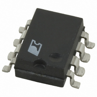
DPA423G-TL
Manufacturer Part Number
DPA423G-TL
Description
IC CONV DC-DC DPA SWITCH 8SMD
Manufacturer
Power Integrations
Series
DPA-Switch®r
Specifications of DPA423G-TL
Applications
Converter, Power Over Ethernet and Telecom Applications
Voltage - Input
16 ~ 75 V
Number Of Outputs
1
Voltage - Output
220V
Operating Temperature
-40°C ~ 125°C
Mounting Type
Surface Mount
Package / Case
8-SMD Gull Wing
For Use With
596-1195 - KIT REF DES DPA 6.6W DC-DC CONV596-1009 - KIT DESIGN ACCELERATOR DC-DC596-1007 - KIT DESIGN ACCELERATOR POE CONV
Lead Free Status / RoHS Status
Request inventory verification / RoHS non-compliant


required for tight DC voltage regulation. Not shown in the
circuit diagram is the ESR of the output capacitors. The ESR
is also an important element in the frequency compensation of
the feedback loop.
Output LC Filter
The filter formed by the output inductor and the output capacitors
contributes two poles to the loop response at the filterʼs resonant
frequency. Since the filter is a resonant circuit with relatively
low loss, the gain and phase change rather abruptly near the
resonant frequency. Consequently, the poles and zeros for
shaping the loop response should either avoid this region or
compensate for the resonance.
Proper placement of the resonant frequency of the output
filter will avoid complications in the design of the feedback
loop. The position of the resonant frequency should allow the
designer to shape the desired response with a limited number of
compensation components of reasonable size. The recommended
resonant frequency for an output filter that uses low ESR
tantalum capacitors in a forward converter with DPA-Switch
and optocoupler feedback is between 4 kHz and 6 kHz. This
value is consistent with the inductor and capacitor values for
desirable ripple current and ripple voltage.
Figure 10. Gain and Phase of a Typical Feedback Loop for DC-DC Forward Converter with DPA-Switch. Markers Show Locations of Major
12
-10
-20
-30
-40
-50
-60
60
50
40
30
20
10
0
0.1
1-Gain
1-Phase
C
7/04
AN-31
Poles and Zeros.
0 Degrees Phase
180 Degrees Phase Margin
P1
1
56 dB Loop Gain
10
Z1
180 Degrees Phase
0 Degrees Phase Margin
Frequency (Hz)
0 dB Gain
100
P2
The output capacitor ESR contributes a zero that compensates for
one of the poles from the filter. However, for low ESR tantalum
or organic electrolyte capacitors, this zero usually occurs too
high in frequency to substantially offset the effects of the filter
within the desired loop bandwidth. In the prototype example, the
output filter capacitors are 100 µF, with a maximum specified
ESR of 100 milliohms. The ESR zero is thus at approximately
16 kHz, well beyond the 4 kHz LC filter resonant frequency.
Actual ESR is approximately 80 milliohms, placing the zero
typically at 20 kHz. In situations where standard low ESR
electrolytic capacitors can be used, the higher ESR may place
the ESR zero at a sufficiently low frequency to add significant
additional phase margin.
DPA-Switch Compensation
The network of C6 and R4 at the CONTROL pin of DPA-Switch
provides compensation for the feedback loop in addition to
other functions. The capacitance of C6 with R4 and its own
ESR plus the impedance of the CONTROL pin impedance
provide a pole in the loop gain, followed by a zero from R4
and the ESR of C6.
Suggested values of C6 are between 47 µF and 100 µF. This
range of values will generally be sufficient to provide desirable
Z2
1 k
Phase Margin
60 Degrees
P3
P4
10 k
Z3
Gain Margin
20 dB
Z4
P5
PI-2878-032603
P6
100 k
270
240
210
180
150
120
90
60
30
0
-30
-60
-90
Related parts for DPA423G-TL
Image
Part Number
Description
Manufacturer
Datasheet
Request
R

Part Number:
Description:
IC CONV DC-DC DPA SWITCH 8SMD
Manufacturer:
Power Integrations
Datasheet:

Part Number:
Description:
Highly Integrated DC-DC Converter Ics For Distributed Power Architecturesthe Dpa-switch ic Family Introduces a Highly Integratedsolution For DC-DC Conversion Applications in The 16-75 Vdcinput Range.dpa-switch Uses The Same Proven Topology as Topswit
Manufacturer:
Power Integrations, Inc.
Datasheet:

Part Number:
Description:
(DPA423 - DPA426) Highly Integrated DC-DC Converter ICs for Distributed Power Architectures
Manufacturer:
Power Integrations
Datasheet:
Part Number:
Description:
SOP-16
Manufacturer:
Power Integrations
Datasheet:
Part Number:
Description:
DIP8
Manufacturer:
Power Integrations
Datasheet: