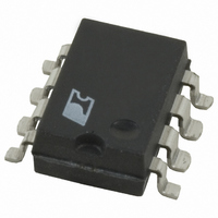
DPA423G-TL Power Integrations, DPA423G-TL Datasheet - Page 4

DPA423G-TL
Manufacturer Part Number
DPA423G-TL
Description
IC CONV DC-DC DPA SWITCH 8SMD
Manufacturer
Power Integrations
Series
DPA-Switch®r
Specifications of DPA423G-TL
Applications
Converter, Power Over Ethernet and Telecom Applications
Voltage - Input
16 ~ 75 V
Number Of Outputs
1
Voltage - Output
220V
Operating Temperature
-40°C ~ 125°C
Mounting Type
Surface Mount
Package / Case
8-SMD Gull Wing
For Use With
596-1195 - KIT REF DES DPA 6.6W DC-DC CONV596-1009 - KIT DESIGN ACCELERATOR DC-DC596-1007 - KIT DESIGN ACCELERATOR POE CONV
Lead Free Status / RoHS Status
Request inventory verification / RoHS non-compliant
Efficiency
Designing a DC-DC converter with DPA-Switch involves
several engineering tradeoffs that weigh efficiency against cost
and complexity. The circuit configuration in Figure 1 achieves
efficiencies greater than 85% over the range of input voltage
at medium loads. In typical applications without synchronous
rectifcation, approximately 25% of the total power loss will be in
the DPA-Switch (see DPA-Switch data sheet), 40% in the output
rectifiers, and 30% in the magnetic devices. The remainder is
distributed among other devices and circuit traces.
Higher efficiencies of approximately 91% can be obtained
when Schottky rectifiers are replaced by synchronous rectifiers,
allowing lower voltage drops. The efficiency can be raised
even higher with the use of the next larger device in the
DPA-Switch family that has lower R
device size may not improve the efficiency due to increased
device switching losses. Losses in the magnetic devices can
be reduced by using larger cores and by switching at 300 kHz
instead of 400 kHz. All these alternatives have compromises in
size, cost and complexity that the designer must evaluate.
Temperature
DC-DC converters usually must operate over an extended
range of temperature that goes beyond the limits for ordinary
consumer electronics. Designers should be aware that the
characteristics of passive components are likely to change
significantly with temperature. Attention to these effects to
choose suitable components can prevent unexpected and
undesirable behavior.
Designers must pay particular attention to the selection of the
output capacitors and the components in the feedback circuit
to guarantee specified performance throughout the temperature
range. The details are addressed later in the sections on Output
Capacitor Selection and Feedback Design.
Bias Voltage
There are four ways to generate the bias voltage required for
operation of DPA-Switch:
(a) DC input derived
(b) Transformer bias (unregulated)
(c) Output coupled inductor winding
(d) Transformer bias (regulated)
Figure 2 illustrates the four alternatives. Each one must provide
a minimum of 8 V at the collector of the optocoupler under worst
case operating conditions (minimum input voltage and minimum
load). The lowest bias voltage under typical conditions should be
12 V. The output coupled inductor and the regulated transformer
bias techniques give the highest efficiency of the four solutions
4
C
7/04
AN-31
DS(ON)
. Further increases in
because the voltage across the optocoupler is controlled. This
is countered by increased complexity. Optocoupler dissipation
can be significant and should be verified. Maximum optocoupler
phototransistor current is equal to the maximum CONTROL
pin current (I
dissipation therefore occurs at the highest bias voltage (highest
input voltage for (a) and (b)) and minimum load. Table 2
provides a comparison of complexity vs performance for all
the solutions.
a) The DC input derived bias is the simplest of the three
b) The transformer bias (unregulated) is created from a winding
c) Output coupled inductor bias uses a winding on the output
d) The transformer bias (regulated) solution peforms the
solutions. It uses a Zener diode between the positive DC input
and the collector of the phototransistor of the optocoupler to
reduce the maximum collector-to-emitter voltage, and more
importantly, to limit the dissipation in the optocoupler. The
penalty for simplicity is a reduction in efficiency that can
be significant at high input voltages. This alternative is best
for industrial applications where the input voltage is low
(18 V to 36 V). The input voltage in industrial applications
is usually low enough to eliminate the Zener diode because
the breakdown voltages for standard optocouplers can be as
high as 70 V. Designers must check the maximum power
dissipation in the optocoupler in either case.
on the power transformer. The forward bias winding
should be connected to the rectifier in a polarity such that it
conducts when the DPA-Switch is on. Since the bias voltage
is proportional to the input voltage, efficiency is reduced at
high input voltages, but the effect is less than with the direct
connection to the input. Again, the designer needs to check
the power dissipation in the optocoupler at the maximum bias
voltage. For this bias type, worst case is minimum output
load and high input voltage. Flyback bias windings are not
recommended for DPA-Switch applications since they will
affect the transformer reset.
inductor to develop the bias voltage. This technique
provides a well regulated bias voltage when the converter
operates in the continuous conduction mode. Regulation
is accomplished by phasing the winding such that the bias
voltage is proportional to the output voltage by transformer
action when the DPA-Switch turns off. The penalty for the
higher efficiency is the cost and complexity of a custom output
inductor. The bias voltage can be adjusted by modifying turns
ratio, bias capacitor size and minimum load on the main
output. The designer should verify a minimum bias voltage
of 8 V at minimum load and maximum input voltage.
same function as the output coupled inductor bias (c). The
bias voltage regulation is not quite as good as with the
output coupled inductor bias. However, the solution does
provide a reasonably constant bias voltage over a variety
C(SKIP)
) for the selected DPA-Switch. Maximum


