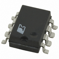
DPA423G-TL Power Integrations, DPA423G-TL Datasheet - Page 2

DPA423G-TL
Manufacturer Part Number
DPA423G-TL
Description
IC CONV DC-DC DPA SWITCH 8SMD
Manufacturer
Power Integrations
Series
DPA-Switch®r
Specifications of DPA423G-TL
Applications
Converter, Power Over Ethernet and Telecom Applications
Voltage - Input
16 ~ 75 V
Number Of Outputs
1
Voltage - Output
220V
Operating Temperature
-40°C ~ 125°C
Mounting Type
Surface Mount
Package / Case
8-SMD Gull Wing
For Use With
596-1195 - KIT REF DES DPA 6.6W DC-DC CONV596-1009 - KIT DESIGN ACCELERATOR DC-DC596-1007 - KIT DESIGN ACCELERATOR POE CONV
Lead Free Status / RoHS Status
Request inventory verification / RoHS non-compliant
Figure 1 shows a typical implementation of DPA-Switch in
a power supply with a single regulated output. This design
guide discusses considerations for selection of components
for a practical implementation of the circuit in Figure 1. It
also addresses options and tradeoffs in cost, efficiency and
complexity that include the substitution of synchronous rectifiers
and alternative generation of the bias voltage.
System Requirements
The design begins with an evaluation of the requirements.
Table 1 gives the specifications for the example converters
described here, that have been constructed and evaluated as
engineering prototypes. Variants of the basic design achieve
higher efficiencies with minor increases in complexity.
Input Voltage Range
The actual input voltage range required for operation of the
converter is greater than that indicated by the specification. The
specification requires the converter to operate and to deliver
full performance at a minimum input of 36 V. Therefore, the
Table 1. Typical Specifications for a Single Output DC-DC Converter.
Input
Input Voltage
Input Voltage UV Turn ON
Input Voltage UV Turn Off
Input Voltage OV Turn On
Input Voltage OV Turn Off
Output
Output Voltage
Output Ripple and Noise
Output Current
Line Regulation
Load Regulation
Transient Response Peak
Deviation
Transient Response Recovery
Total Output Power
Continuous Output Power
Efficiency
Low-Cost Design
Enhanced (non-sync rect.)
Synchronous Rectified Design
Environmental
Input-Output Isolation Voltage
Ambient Temperature
2
C
7/04
AN-31
Description
Symbol
η
η
V
Enhanced
V
P
η
SyncRect
T
I
RIPPLE
V
OUT
Cost
AMB
OUT
OUT
IN
1500
Min
4.8
-40
36
29
0
5.00
±0.2
±0.5
Typ
200
48
50
84
87
91
3
designer must guarantee that the converter becomes active and
fully functional at a voltage that is lower than the minimum.
Tolerance variations of the Line Undervoltage Threshold of
DPA-Switch with prudent design margin put the practical
minimum operating voltage closer to 30 V. Similarly, the
converter must be designed to operate at voltages higher than
the maximum specified input. The actual input voltage range
should be considered to be from about 30 V to 90 V for the
typical nominal input voltage of 48 VDC.
Output Characteristics
The output voltage can be maintained to ±4% over the range of
line, load and operational temperature range with an ordinary
feedback circuit that uses a TL431 regulator. Transient response
is controlled with proper frequency compensation. The design of
the feedback network with guidance for selection of component
values is addressed in a separate section. Ripple and noise are
strongly influenced by the size of the output inductor and the
choice of output capacitors. These topics are discussed more
thoroughly later in this document.
Max
6.00
5.2
75
36
72
90
30
85
Units
VDC
VDC
VDC
VDC
VDC
VDC
% of
V
mV
µs
°C
W
%
%
%
%
%
V
A
OUT
50-75% load step, 48 VDC input
50-75% Load step, 100 mA/µs
To 1% of final output voltage,
Free convection, sea level
Measured at P
Typical operational range
25 °C, 48 VDC Input
20 MHz Bandwidth
48 VDC input
Comment
±4%
OUT
(30 W),


