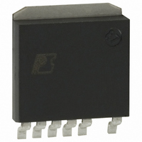
DPA423SN Power Integrations, DPA423SN Datasheet - Page 14

DPA423SN
Manufacturer Part Number
DPA423SN
Description
IC CONV DC-DC DPA SWITCH SPAK
Manufacturer
Power Integrations
Series
DPA-Switch®r
Specifications of DPA423SN
Applications
Converter, Power Over Ethernet and Telecom Applications
Voltage - Input
16 ~ 75 V
Number Of Outputs
1
Voltage - Output
220V
Operating Temperature
-40°C ~ 125°C
Mounting Type
Surface Mount
Package / Case
SPak (5 leads + Tab)
Mounting Style
SMD/SMT
For Use With
596-1195 - KIT REF DES DPA 6.6W DC-DC CONV
Lead Free Status / RoHS Status
Lead free / RoHS Compliant
Available stocks
Company
Part Number
Manufacturer
Quantity
Price
Company:
Part Number:
DPA423SN
Manufacturer:
POWER
Quantity:
15 000
Part Number:
DPA423SN
Manufacturer:
POWER
Quantity:
20 000
Company:
Part Number:
DPA423SN-TL
Manufacturer:
IDT
Quantity:
200
Part Number:
DPA423SN-TL
Manufacturer:
POWER
Quantity:
20 000
Figure 11. Example of DPA-Switch in a Single-Ended DC-DC Forward Converter with Synchronous Rectification.
The magnitude of the gain at frequencies greater than Z1 is related
directly to the current transfer ratio (CTR) of the optocoupler.
Therefore, the CTR must be controlled to maintain a stable and
well-behaved system. Designers should choose an optocoupler
that has a CTR in the range of 100% to 200% at the maximum
CONTROL pin current of 12 mA. The phototransistor of the
optocoupler must also have a breakdown voltage greater than
the maximum bias voltage.
Figure 10 shows that this example has a desirable phase margin
of 60 degrees and a comfortable gain margin of 20 dB. Sufficient
margin is required in the design of the feedback loop to allow
for tolerances in the CTR of the optocoupler, changes in ESR
of the output capacitor, and the change in gain with operating
voltage. The ESR can change significantly with temperature.
This should be a primary consideration in the selection of output
capacitors. The design must also allow for tolerance variations
in all other components.
Operation at No Load
Those who design or specify DC-DC converters should
pay particular attention to requirements for minimum load.
The control characteristics are different for operation in the
continuous conduction mode (moderate to heavy loads) and
discontinuous conduction mode (light loads). The boundary
between the two modes occurs at the load where K
synchronous rectification).
14
36-75 VDC
+
V
V
C
7/04
AN-31
IN
IN
C1, C2 & C3
2.5 A
100 V
1 µH
1 µF
L1
SMBJ
VR1
150
D
619 kΩ
S
1%
R1
CONTROL
CONTROL
X
18.2 kΩ
L
1%
R3
F
C
DPA-Switch
U1
DPA425R
1.5 kV
1 nF
220 nF
∆I
C7
T1
C5
= 2 (without
10 Ω
R17
10 Ω
R15
Si4888
10 Ω
R14
Q2
DY
68 µF
1.0 Ω
10 V
C6
R4
3300 pF
10 kΩ
R16
C17
D4
BAV19WS
The two modes have different control characteristics. The
converter in discontinuous conduction mode will usually have
a slower response to transients and higher ripple voltage at the
output than in continuous conduction mode. In extreme cases, a
converter that is well-behaved in continuous conduction mode
may actually become unstable at light load or with no load
unless correctly designed. Many commercial DC-DC converter
modules specify a large minimum load to prevent operation in
discontinuous conduction mode.
A converter that operates deeply in discontinuous conduction
mode requires a very small duty ratio. Operation at very light
loads is not a problem for DPA-Switch because it automatically
reduces the effective switching frequency by skipping cycles
to give duty ratios less than about 5%.
Operation at small duty ratios requires a larger capacitor to
keep the bias voltage above its minimum required value of
8 V. In a trade-off with size, cost and efficiency, the best solution
to a requirement to operate with no load is to include a small
preload in parallel with the output capacitors. The amount of
the load is determined empirically to supplement the natural
loading from the other small-signal circuits that get their power
from the output.
Synchronous Rectification
The use of synchronous rectification can yield a substantial
increase in efficiency over passive Schottky rectifiers on the
Si4888
PC357N1T
Q1
DY
U2
4.7 µF
D2
20 V
C4
19WS
BAV
D1
L2
10 kΩ
10 µF
LM431AIM3
BAV19WS
10 V
R7
C13
D3
U3
150 Ω
U2
R6
100 µF
10 V
C10
100 µF
10 V
C11
100 nF
5.1 Ω
R12
C16
1 µF
C14
1 µF
10 V
C12
10.0 kΩ
10.0 kΩ
220 Ω
R10
R11
1%
1%
R9
PI-3472-040903
5 V, 6 A
RTN


