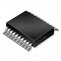
IRU3018CW International Rectifier, IRU3018CW Datasheet - Page 11

IRU3018CW
Manufacturer Part Number
IRU3018CW
Description
IC CTRL/REG SYNC BUCK 24-SOIC
Manufacturer
International Rectifier
Datasheet
1.IRU3018CW.pdf
(18 pages)
Specifications of IRU3018CW
Applications
Controller, Intel Pentium® II
Voltage - Input
5V, 12V
Number Of Outputs
3
Voltage - Output
1.3 ~ 5.5 V
Operating Temperature
0°C ~ 70°C
Mounting Type
Surface Mount
Package / Case
24-SOIC (7.5mm Width)
Lead Free Status / RoHS Status
Contains lead / RoHS non-compliant
Other names
*IRU3018CW
IRU3018-CW
IRU3018-CW
IRU3018-CW
IRU3018-CW
Available stocks
Company
Part Number
Manufacturer
Quantity
Price
Part Number:
IRU3018CW
Manufacturer:
IR
Quantity:
20 000
APPLICATION INFORMATION
An example of how to calculate the components for the
application circuit is given below.
Assuming, two set of output conditions that this regula-
tor must meet for Vcore:
The regulator design will be done such that it meets the
worst case requirement of each condition.
Output Capacitor Selection
The first step is to select the output capacitor. This is
done primarily by selecting the maximum ESR value
that meets the transient voltage budget of the total DVo
specification. Assuming that the regulators DC initial
accuracy plus the output ripple is 2% of the output volt-
age, then the maximum ESR of the output capacitor is
calculated as:
The Sanyo MVGX series is a good choice to achieve
both the price and performance goals. The 6MV1500GX,
1500mF, 6.3V has an ESR of less than 36mV typical.
Selecting 6 of these capacitors in parallel has an ESR
of
Other type of Electrolytic capacitors from other manu-
facturers to consider are the Panasonic FA series or the
Nichicon PL series.
Reducing the Output Capacitors Using Voltage Level
Shifting Technique
The trace resistance or an external resistor from the output
of the switching regulator to the Slot 1 can be used to
the circuit advantage and possibly reduce the number of
output capacitors, by level shifting the DC regulation point
when transitioning from light load to full load and vice
versa. To accomplish this, the output of the regulator is
typically set about half the DC drop that results from
light load to full load. For example, if the total resistance
from the output capacitors to the Slot 1 and back to the
Gnd pin of the IRU3018 is 5mV and if the total DI, the
change from light load to full load is 14A, then the output
voltage measured at the top of the resistor divider which
is also connected to the output capacitors in this case,
must be set at half of the 70mV or 35mV higher than the
DAC voltage setting. This intentional voltage level shift-
Rev. 1.6
07/16/02
a) Vo=2.8V, Io=14.2A, DVo=185mV, DIo=14.2A
b) Vo=2V, Io=14.2A, DVo=140mV, DIo=14.2A
ESR [
6mV which achieves our low ESR goal.
14.2
100
= 7mV
www.irf.com
ing during the load transient eases the requirement for
the output capacitor ESR at the cost of load regulation.
One can show that the new ESR requirement eases up
by half the total trace resistance. For example, if the
ESR requirement of the output capacitors without volt-
age level shifting must be 7mV then after level shifting
the new ESR will only need to be 8.5mV if the trace
resistance is 5mV (7+5/2=9.5). However, one must be
careful that the combined “voltage level shifting” and the
transient response is still within the maximum tolerance
of the Intel specification. To insure this, the maximum
trace resistance must be less than:
For example, assuming:
Then the Rs is calculated to be:
However, if a resistor of this value is used, the maximum
power dissipated in the trace (or if an external resistor is
being used) must also be considered. For example if
Rs=12.6mV, the power dissipated is:
This is a lot of power to be dissipated in a system. So, if
the Rs=5mV, then the power dissipated is about 1W
which is much more acceptable. If level shifting is not
implemented, then the maximum output capacitor ESR
was shown previously to be 7mV which translated to 6
of the 1500mF, 6MV1500GX type Sanyo capacitors. With
Rs=5mV, the maximum ESR becomes 9.5mV which is
equivalent to
is that if a trace is being used to implement the resistor,
the power dissipated by the trace increases the case
temperature of the output capacitors which could seri-
ously effect the life time of the output capacitors.
Rs [ 23(Vspec - 0.023Vo - DVo) / DI
Where:
Rs = Total maximum trace resistance allowed
Vspec = Intel total voltage spec
Vo = Output voltage
DVo = Output ripple voltage
DI = load current step
Vspec = 140mV = 0.1V for 2V output
Vo = 2V
DVo = assume 10mV = 0.01V
DI = 14.2A
Rs [ 23(0.140 - 0.0232 - 0.01) / 14.2 = 12.6mV
Io
2
3Rs = 14.2
4 caps. Another important consideration
2
312.6 = 2.54W
IRU3018
11


