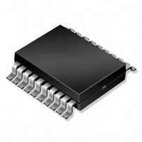
IRU3018CW International Rectifier, IRU3018CW Datasheet - Page 5

IRU3018CW
Manufacturer Part Number
IRU3018CW
Description
IC CTRL/REG SYNC BUCK 24-SOIC
Manufacturer
International Rectifier
Datasheet
1.IRU3018CW.pdf
(18 pages)
Specifications of IRU3018CW
Applications
Controller, Intel Pentium® II
Voltage - Input
5V, 12V
Number Of Outputs
3
Voltage - Output
1.3 ~ 5.5 V
Operating Temperature
0°C ~ 70°C
Mounting Type
Surface Mount
Package / Case
24-SOIC (7.5mm Width)
Lead Free Status / RoHS Status
Contains lead / RoHS non-compliant
Other names
*IRU3018CW
IRU3018-CW
IRU3018-CW
IRU3018-CW
IRU3018-CW
Available stocks
Company
Part Number
Manufacturer
Quantity
Price
Part Number:
IRU3018CW
Manufacturer:
IR
Quantity:
20 000
PIN#
Rev. 1.6
07/16/02
10
12
13
14
15
16
17
18
19
20
21
22
23
24
11
PIN SYMBOL
Fault / Rt
OCSet1
Phase1
UGate1
LGate1
Gate3
V
V
PGnd
V
Gnd
Fb2
Fb3
Fb1
En
OUT
SEN
IN
2
1
2
This pin has dual function. It acts as an output of the OVP circuitry or it can be used to
program the frequency using an external resistor. When used as a fault detector, if the
switcher output exceeds the OVP trip point, the Fault pin switches to 12V and the soft-
start cap is discharged. If the Fault pin is to be connected to any external circuitry, it
needs to be buffered as shown in the application circuit.
This pin provides the feedback for the internal LDO regulator which its output is V
This pin is the input that provides power for the internal LDO regulator. It is also monitored
for the under-voltage and over-voltage conditions.
This pin is the output of the internal LDO regulator.
This pin serves as the ground pin and must be connected directly to the ground plane.
This pin controls the gate of an external transistor for the 1.5V GTL+ linear regulator.
This pin provides the feedback for the linear regulator which its output drive is Gate3.
This pin is a TTL compatible Enable pin. When this pin is left open or pulled high, the
device is enabled and when it is pulled low, it will disable the switcher and the LDO
controller (V
enable the device, both switcher and V
start-up.
This pin provides the feedback for the synchronous switching regulator. Typically this pin
can be connected directly to the output of the switching regulator. However, a resistor
divider is recommended to be connected from this pin to V
output voltage for any drop in the output voltage that is caused by the trace resistance.
The value of the resistor connected from V
This pin is internally connected to the under-voltage and over-voltage comparators sens-
ing the Vcore status. It must be connected directly to the Vcore supply.
This pin is connected to the Drain of the power MOSFET of the Core supply and it provides
the positive sensing for the internal current sensing circuitry. An external resistor pro-
grams the CS threshold depending on the R
tor is placed in parallel with the programming resistor to provide high frequency noise
filtering.
This pin serves as the Power ground pin and must be connected directly to the ground
plane close to the source of the synchronous MOSFET. A high frequency capacitor (typi-
cally 1mF) must be connected from V12 pin to this pin for noise free operation.
Output driver for the synchronous power MOSFET for the Core supply.
This pin is connected to the Source of the power MOSFET for the Core supply and it
provides the negative sensing for the internal current sensing circuitry.
Output driver for the high side power MOSFET for the Core supply.
PIN DESCRIPTION
OUT
3) leaving the internal 200mA regulator operational. When signal is given to
www.irf.com
OUT
3 will go through soft-start, the same as during
OUT
DS
1 to Fb1 must be less than 100V.
of the power MOSFET. An external capaci-
OUT
1 and Gnd to adjust the
IRU3018
OUT
4.
5


