IRU3018CW International Rectifier, IRU3018CW Datasheet - Page 14
IRU3018CW
Manufacturer Part Number
IRU3018CW
Description
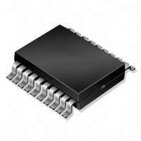
IC CTRL/REG SYNC BUCK 24-SOIC
Manufacturer
International Rectifier
Datasheet
1.IRU3018CW.pdf
(18 pages)
Specifications of IRU3018CW
Applications
Controller, Intel Pentium® II
Voltage - Input
5V, 12V
Number Of Outputs
3
Voltage - Output
1.3 ~ 5.5 V
Operating Temperature
0°C ~ 70°C
Mounting Type
Surface Mount
Package / Case
24-SOIC (7.5mm Width)
Lead Free Status / RoHS Status
Contains lead / RoHS non-compliant
Other names
*IRU3018CW
IRU3018-CW
IRU3018-CW
IRU3018-CW
IRU3018-CW
Available stocks
Company
Part Number
Manufacturer
Quantity
Price

Part Number:
IRU3018CW
Manufacturer:
IR
Quantity:
20 000


IRU3018
For 1.5V supply
Assuming R
For 2.5V supply
Assuming R
Switcher Output Voltage Adjust
As it was discussed earlier, the trace resistance from
the output of the switching regulator to the Slot 1 can be
used to the circuit advantage and possibly reduce the
number of output capacitors, by level shifting the DC
regulation point when transitioning from light load to full
load and vice versa. To account for the DC drop, the
output of the regulator is typically set about half the DC
drop that results from light load to full load. For example,
if the total resistance from the output capacitors to the
Slot 1 and back to the Gnd pin of the IRU3018 is 5mV
and if the total DI, the change from light load to full load
is 14A, then the output voltage measured at the top of
the resistor divider which is also connected to the out-
put capacitors in this case, must be set at half of the
70mV or 35mV higher than the DAC voltage setting. To
do this, the top resistor of the resistor divider (R17 in the
application circuit) is set at 100V, and the R19 is calcu-
lated. For example, if DAC voltage setting is for 2.8V
and the desired output under light load is 2.835V, then
R19 is calculated using the following formula:
Note: The value of the top resistor must not exceed 100V.
The bottom resistor can then be adjusted to raise the
output voltage.
Soft-Start Capacitor Selection
The soft-start capacitor must be selected such that dur-
ing the start-up when the output capacitors are charging
up, the peak inductor current does not reach the current
limit threshold. A minimum of 1mF capacitor insures this
for most applications. An internal resistor charges the
soft-start capacitor which slowly ramps up the inverting
input of the PWM comparator V
output voltage to ramp at the same rate as the soft-start
14
Rt = R
Rt = 1003 (1.5/1.26) - 1 = 19.1V
Rt = R
Rt = 2003 (2.5/1.26) - 1 = 197V
Select Rt=200V
R19 = 1003 V
R19 = 1003 2.8/(2.835 - 1.00432.800) = 11.76KV
Select 11.8KV, 1%
B
B
3 (Vo/V
3 (Vo/V
B
B
=100V
=200V
DAC
REF
REF
/(Vo - 1.0043V
) - 1
) - 1
FB
3. This insures the
DAC
)
(V)
www.irf.com
cap thereby limiting the input current. For example, with
1mF of soft-start capacitor, the ramp up rate is approxi-
mated to be 1V/20ms. For example if the output capaci-
tance is 9000mF, the maximum start up current will be:
The other function of the soft-start cap is to provide an
off time between the current limit cycles(HICCUP) in or-
der for the synchronous MOSFET to cool off and survive
the short circuit condition. The off time between the cur-
rent limit cycles is approximated as:
Input Filter
It is recommended to place an inductor between the
system 5V supply and the input capacitors of the switch-
ing regulator to isolate the 5V supply from the switching
noise that occurs during the turn on and off of the switch-
ing components. Typically an inductor in the range of 1
to 3mH will be sufficient in this type of application.
External Shutdown
The best way to shutdown the IRU3018 is to pull down
on the soft-start pin using an external small signal tran-
sistor such as 2N3904 or 2N7002 small signal MOSFET.
This allows slow ramp up of the output, the same as the
power up.
Layout Considerations
Switching regulators require careful attention to the lay-
out of the components, specifically power components
since they switch large currents. These switching com-
ponents can create large amount of voltage spikes and
high frequency harmonics if some of the critical compo-
nents are far away from each other and are connected
with inductive traces. The following is a guideline of how
to place the critical components and the connections
between them in order to minimize the above issues.
Start the layout by first placing the power components:
1) Place the input capacitor C14 and the high-side
2) Place the synchronous MOSFET, Q4 and the Q3 as
3) Place the snubber R15 & C13 between Q4 & Q3.
MOSFET, Q3 as close to each other as possible.
close to each other as possible with the intention
that the source of Q3 and drain of the Q4 has the
shortest length.
I = 9000mF3(1V/20ms) = 0.45A
T
For example if Css=1mF, T
HICCUP
= 603Css
(ms)
HICCUP
= 6031 = 60ms
07/16/02
Rev. 1.6
Related parts for IRU3018CW
Image
Part Number
Description
Manufacturer
Datasheet
Request
R

Part Number:
Description:
SCHOTTKY RECTIFIER
Manufacturer:
International Rectifier Corp.
Datasheet:
Part Number:
Description:
SCHOTTKY RECTIFIER
Manufacturer:
International Rectifier Corp.
Datasheet:
Part Number:
Description:
SCHOTTKY RECTIFIER
Manufacturer:
International Rectifier Corp.
Datasheet:
Part Number:
Description:
SCHOTTKY RECTIFIER
Manufacturer:
International Rectifier Corp.
Datasheet:
Part Number:
Description:
SCHOTTKY RECTIFIER
Manufacturer:
International Rectifier Corp.
Datasheet:
Part Number:
Description:
SCHOTTKY RECTIFIER
Manufacturer:
International Rectifier Corp.
Datasheet:
Part Number:
Description:
SCHOTTKY RECTIFIER
Manufacturer:
International Rectifier Corp.
Datasheet:
Part Number:
Description:
SCHOTTKY RECTIFIER
Manufacturer:
International Rectifier Corp.
Datasheet:
Part Number:
Description:
SCHOTTKY RECTIFIER
Manufacturer:
International Rectifier Corp.
Datasheet:
Part Number:
Description:
SCHOTTKY RECTIFIER
Manufacturer:
International Rectifier Corp.
Datasheet:
Part Number:
Description:
SCHOTTKY RECTIFIER
Manufacturer:
International Rectifier Corp.
Datasheet:
Part Number:
Description:
SCHOTTKY RECTIFIER
Manufacturer:
International Rectifier Corp.
Datasheet:
Part Number:
Description:
SCHOTTKY RECTIFIER
Manufacturer:
International Rectifier Corp.
Datasheet:
Part Number:
Description:
SCHOTTKY RECTIFIER
Manufacturer:
International Rectifier Corp.
Datasheet:
Part Number:
Description:
SCHOTTKY RECTIFIER
Manufacturer:
International Rectifier Corp.
Datasheet: