LM2664M6/NOPB National Semiconductor, LM2664M6/NOPB Datasheet - Page 5
LM2664M6/NOPB
Manufacturer Part Number
LM2664M6/NOPB
Description
IC SW CAP/INV ADJ 40MA SOT23-6
Manufacturer
National Semiconductor
Type
Switched Capacitor (Charge Pump), Invertingr
Datasheet
1.LM2664M6NOPB.pdf
(9 pages)
Specifications of LM2664M6/NOPB
Internal Switch(s)
Yes
Synchronous Rectifier
No
Number Of Outputs
1
Voltage - Output
-1.8 ~ -5.5 V
Current - Output
40mA
Frequency - Switching
160kHz
Voltage - Input
1.8 ~ 5.5 V
Operating Temperature
-40°C ~ 85°C
Mounting Type
Surface Mount
Package / Case
SOT-23-6
Power - Output
600mW
Primary Input Voltage
5V
No. Of Outputs
1
Output Voltage
-5.5V
Output Current
40mA
No. Of Pins
6
Operating Temperature Range
-40°C To +85°C
Msl
MSL 1 - Unlimited
Filter Terminals
SMD
Rohs Compliant
Yes
Lead Free Status / RoHS Status
Lead free / RoHS Compliant
Other names
LM2664M6
LM2664M6TR
LM2664M6TR
Available stocks
Company
Part Number
Manufacturer
Quantity
Price
Company:

Part Number:
LM2664M6/NOPB
Manufacturer:
SAMSUNG
Quantity:
3 400


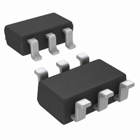
Connection Diagrams
6-Lead Small Outline Package (M6)
Ordering Information
Note 11: The first letter "S" identifies the part as a switched capacitor converter. The next two numbers are the device number. The fourth letter "A" indicates the
grade. Only one grade is available. Larger quantity reels are available upon request.
Pin Descriptions
Circuit Description
The LM2664 contains four large CMOS switches which are
switched in a sequence to invert the input supply voltage.
Energy transfer and storage are provided by external capaci-
tors. Figure 2 illustrates the voltage conversion scheme.
When S
voltage V+. During this time interval, switches S
open. In the second time interval, S
same time, S
number of cycles, the voltage across C
V+. Since the anode of C
at the cathode of C
current. The output voltage drop when a load is added is
determined by the parasitic resistance (R
FET switches and the ESR of the capacitors) and the charge
transfer loss between capacitors. Details will be discussed in
the following application information section.
Pin
1
2
3
4
5
6
Order Number
LM2664M6X
LM2664M6
1
and S
2
Top View With Package Marking
Name
CAP−
CAP+
GND
OUT
and S
SD
V+
3
are closed, C
2
4
equals −(V+) when there is no load
are closed, C
2
Package Number
Power supply ground input.
Negative voltage output.
Connect this pin to the negative terminal of the charge-pump capacitor.
Shutdown control pin, tie this pin to V+ in normal operation, and to GND for shutdown.
Power supply positive voltage input.
Connect this pin to the positive terminal of the charge-pump capacitor.
is connected to ground, the output
MA06A
MA06A
10003104
1
1
1
charges to the supply
and S
is charging C
2
ds(on)
will be pumped to
3
are open; at the
Package Marking
SO3A (Note 11)
SO3A (Note 11)
2
of the MOS-
and S
2
. After a
4
are
5
Tape and Reel (1000 units/rail)
Tape and Reel (3000 units/rail)
Function
FIGURE 2. Voltage Inverting Principle
Supplied as
Actual Size
10003122
www.national.com
10003105
Related parts for LM2664M6/NOPB
Image
Part Number
Description
Manufacturer
Datasheet
Request
R

Part Number:
Description:
DC/DC Charge Pump Converter IC
Manufacturer:
National Semiconductor
Datasheet:
Part Number:
Description:
National Semiconductor [8-Bit D/A Converter]
Manufacturer:
National Semiconductor
Datasheet:
Part Number:
Description:
National Semiconductor [Media Coprocessor]
Manufacturer:
National Semiconductor
Datasheet:
Part Number:
Description:
Digitally Controlled Tone and Volume Circuit with Stereo Audio Power Amplifier, Microphone Preamp Stage and National 3D Sound
Manufacturer:
National Semiconductor
Datasheet:
Part Number:
Description:
Digitally Controlled Tone and Volume Circuit with Stereo Audio Power Amplifier, Microphone Preamp Stage and National 3D Sound
Manufacturer:
National Semiconductor
Datasheet:
Part Number:
Description:
AC97 Rev 2 Codec with Sample Rate Conversion and National 3D Sound
Manufacturer:
National Semiconductor
Part Number:
Description:
Manufacturer:
National Semiconductor
Datasheet:
Part Number:
Description:
Manufacturer:
National Semiconductor
Datasheet:
Part Number:
Description:
General Purpose, Low Voltage, Low Power, Rail-to-Rail Output Operational Amplifiers
Manufacturer:
National Semiconductor
Datasheet:
Part Number:
Description:
8-bit 20 MSPS flash A/D converter.
Manufacturer:
National Semiconductor
Datasheet:
Part Number:
Description:
Low Noise Quad Operational Amplifier
Manufacturer:
National Semiconductor
Datasheet:
Part Number:
Description:
Quad Differential Line Receivers
Manufacturer:
National Semiconductor
Datasheet:
Part Number:
Description:
Quad High Speed Trapezoidal? Bus Transceiver
Manufacturer:
National Semiconductor
Datasheet:
Part Number:
Description:
Dual Line Receiver
Manufacturer:
National Semiconductor
Datasheet: